| Design |
| Development |
[19-SEP-25] The following files describe the design of the A3026 H-BCAM Side Head.
[17-JAN-13] We test the A302601A and find that pins 1 and 3 on U1-U4 are swapped due to an error in the SOT-23 footprint used for the board. Laser diode LD2 pins 3 and 2 are swapped due to an error in the schematic.
[11-MAR-13] When we flash the LEDs on the A302601B, light shines through the circuit board, which has no ground plane, and off the edges of the camera aperture, and back to the image sensor. We cover the LED side of the circuit board with black nail polish, and cover the LEDs themselves also. We wash the nail polish off the tops of the LEDs later. With this arrangement, we can flash the LEDs and see a retroreflecting target 3 m away without washing out the image with direct light from the flash.
[25-MAR-13] We solve the problem of white LED flash illumination shining straight back onto the image sensor by applying black nail polish to the front side of the circuit board, under the LEDs, and around the LED packages, so that only the domed tops of the LEDs can shine light. This method, developed by Guillaume, stops light getting back into the chassis. The A3025A is made with a circuit board lacking a ground plane, and so is translucent.
We make the following observation about the A302601C printed circuit board for the Blue H-BCAM. "There is an issue with the layout of the H-BCAM side boards (A302601C). The problem is that R12 and R13 are too close to J1 and consequently J1 cannot be placed completely flat on the board. It is possible to have it slightly slanted and it looks like it can work just fine. Nevertheless, if at all possible, I would recommend moving future J1 slot(s) just a few millimeters to the right (away from R12 and R13)."
[27-MAR-13] On both the A302601B and A302601C the LEDs are placed in two orientations, so that the anode is for two of them on the left and for the other two on the right.
We try out the A302601C, which has a ground plane, with the flash LEDs. Despite the ground plane, we still must black out the white LEDs. We paint around the cylindrical parts of their bodies with nail polish and we obtain perfect light isolation. Thus the ground plane stops light passing through the board, as we had hoped.
[25-SEP-13] We have an order for 28 BCAM-HLD and 28 BCAM-HRD, so we need to make around 60 each of the side heads. We will fix the various problems with the side heads by creating two new printed circuit boards, the A302601L for the BCAM-HLD, and the A302601R for the BCAM-HRD. These will have a ground plane for light shielding, and place both calibration resistors on the bottom side in a convenient location once the board is installed.
[30-DEC-15] We have an order for 12 BCAM-HRD. We have in hand 28 of the A3026R. We equip them with the ADL65074TL1 7-mW 650-nm laser. We use an SD445 photodiode to measure laser output power directly. To set red light output to 5-6 mW we want the photocurrent between 2.0-2.4 mA. We get the right output power with two 33 kΩ resistors in parallel in place of R6 and R13.
[12-JAN-16] When we press the lasers into our Blue H-BCAM end-walls, we get 84% of the laser light on our photodiode. During H-BCAM production we adjust the photoresistor so that our photodiode current is between 1.7-2.0 mA to get laser power 5-6 mW.
[21-APR-21] We are loading Arima ADL-65074TL 7-mW 650-nm lasers onto A3026L boards and setting them to 4-6 mW output power as measured at the front face of the H-BCAM mounting flange. Of twelve lasers loaded into three BCAM-HLD, average power is 5.36 mW with range 5.28-5.70 mW.
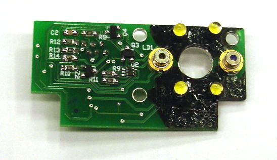
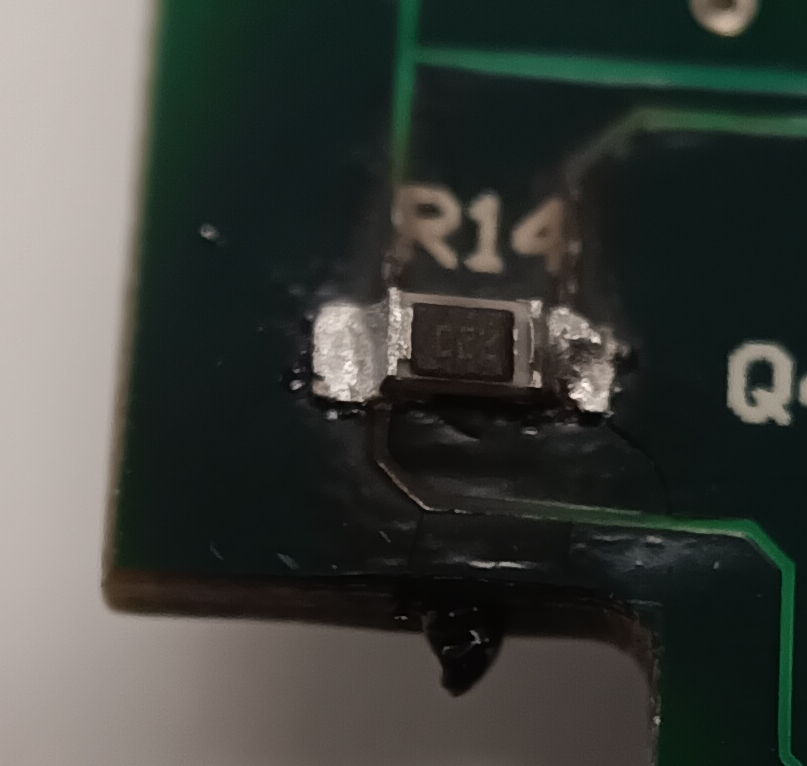
[13-APR-22] We have three H-BCAMs returned from FNL. Two of them, R0213 and R0214, have all four lasers damaged. They were calibrated and shipped at 5 mW output, now emit 0-2 mW depending upon the laser. We see evidence of over-heating in Q1-Q4. The SOT-23 package is discolored. The solder is dull and crinkled on the surface. Resistors R7 and R14 are discolored or charred.
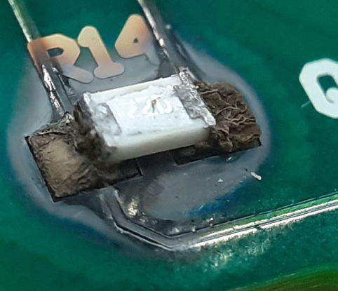
If the laser fails as a short circuit, the drive circuit will apply the maximum current it can through the laser. We could see up to 200 mA flowing through R7 or R14, dissipating 1 W, which will soon burn the P0805 resistor. We can think of only one explanation for these failures: the lasers were left on for several thousand hours.
[24-SEP-25] Our new A302601L printed circuit board has a black solder mask and comes in a 3 × 5 panel. We use it to make 90 of the A3026LV1.
[10-FEB-26] We have returned from Fermi National Laboratory (FNL) H-BCAM C0603, shipped to FNL in 2023. No lasers working, cameras both working. Take apart, find both laser boards are burned up around the laser current limiting resistors. Laser cans have leaked solder, which suggests they heated to above 180°C. The printed circuit board became so hot it charred. Epoxy resin vaporized and condensed on the end walls. There is a dent in the flat beneath the BCAM and the anodizing has been scraped away around the mounting hole on the cover.
We replace both laser boards and load fresh lasers and LEDs. The H-BCAM now appears to be fully functional. Clean CCDs and reassemble. Leave to burn in taking images and flashing lasers.