 LWDAQ Archive

© 2004-2021 Kevan Hashemi, Brandeis University© 2016 Kimberly Rigger, Brandeis University
© 2021-2026 Kevan Hashemi, Open Source Instruments Inc.
| Introduction |
| Cable-Making |
[29-JAN-26] Here we provide an archive of out-of-date instructions and part numbers for LWDAQ systems.
[29-JAN-26] In 2016, we switched to new parts. You may still have some of these parts left over from before the change. The old parts included
You can follow the same procedure for producing white cables as you would for new black cables with the following changes:
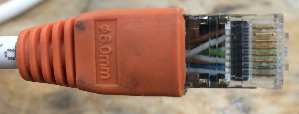
The finished product should look like the photo below.
The old blue cables can be produced in exactly the same way as the new ones, with the exception of the attachment of the strain relief. It is more important with the old connectors that more of the jacket is removed so that the metal teeth of the connector do not oxidize and affect the solid wires.
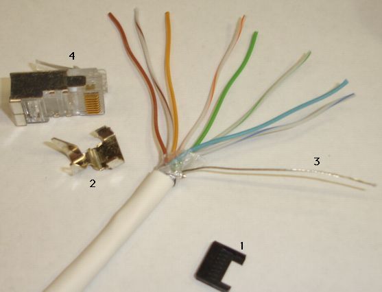
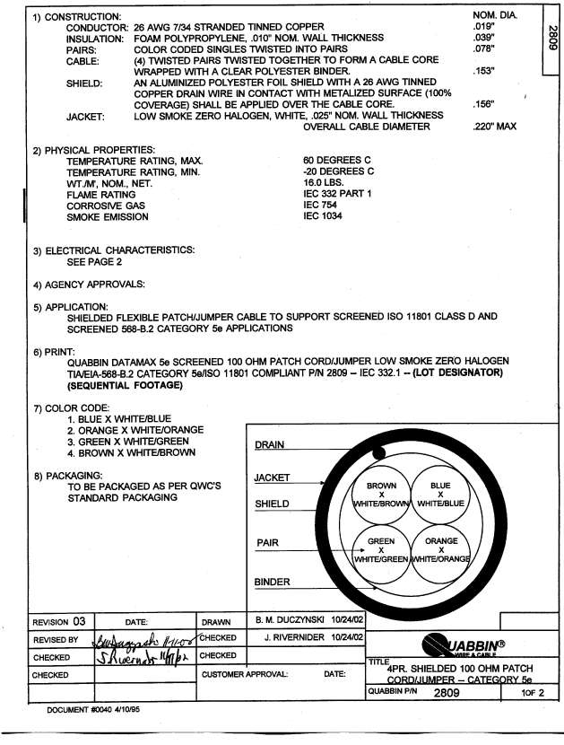
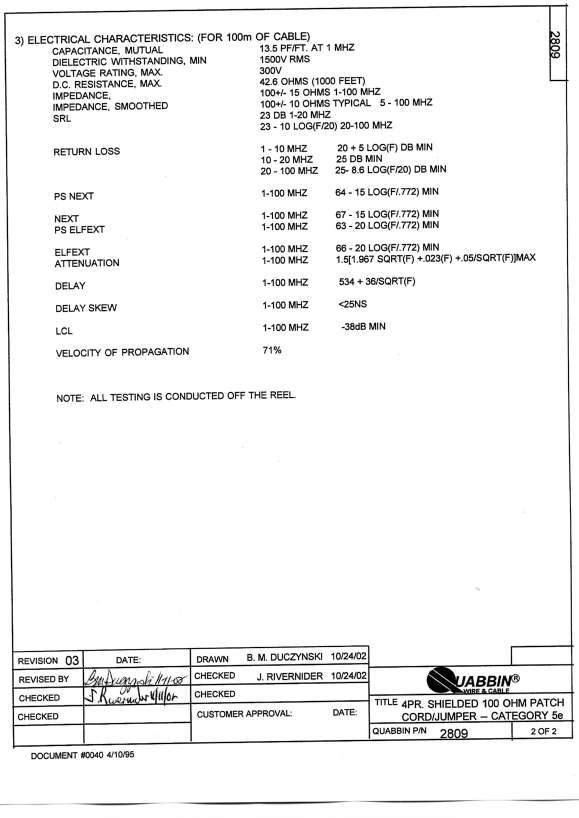
Before 2016, we used parts that differ from the ones listed above. You may still have some of these parts from previous kits. Below are the specifications for each of the old parts. Our stranded cable was a white halogen-free stranded CAT-5 cable, part number 2809 (data sheet pages one and two) from manufacturer Quabbin, which we bought from distributor Anixter. Halogen-free cable is unusual in the United States, so this cable had a 25,000-ft minimum order.
Manufacturer Part Number: 2809
Manufacturer: Quabbin Wire and Cable, USA
Conductor: stranded tinned copper
Insulation: foam polypropylene
Shield: aluminized polyester foil
Drain Wire: 26 AWG solid tinned
Jacket Diameter: 5.6 mm max
Jacket: low-smoke zero halogen
Operating Temperature: 60 C max
Flame Rating: IEC 332 part 1
Corrosive Gas: IEC 754
Smoke Emission: IEC 1034
Jacket Tensile: 2000psi min
Jacket Elongation: 160 % min
Tear Resistance (per ASTM D1004): 35 lb/in min.
Price in 2015: 1.38 $/m
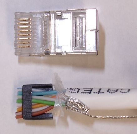
The white cable provided a foil shield and drain wire. We used the drain wire and a seperate metal strain relief part to connect the cable shield to the shield of a modular plug. The modular plug we recommended for all white LWDAQ cables was the 5-569552-3 from Amp (Part number A9111-ND from Digi-Key). This plug comes with a load bar, which is the black part shown below. This load bar does not have individual slots for each wire, but rather has one long slot into which all wires must be inserted in order. This connector is obsolete and have been discontinued.
Along with the shielded plug, we used a seperate strain relief, part number 558527-1 from Amp (Part number A9130-ND from Digi-Key). The strain relief holds the cable jacket firmly, and presses against the cable's drain wire, so that we have reliable connection between the cable shield and the connector shield. This strain relief must be attached seperately to the connector and the cable jacket after the connector is crimped.
Manufacturer Part Number: 5-569552-3
Digi-Key Part Number: A9111-ND
Manufacturer: AMP/Tyco Electronics, USA
Description: modular plug, shielded, 8-way, with load bar.
For Cable Type: round cable
For Conductor Type: stranded wire
Approximate Price: $1 each
Our blue cable has not changed. However, we used to use different connectors for the stranded and solid wires. The modular plug we used for all blue LWDAQ cables is the 5-569530-3 from Amp (A9115-ND from Digi-Key).
Manufacturer Part Number: 5-569530-3
Digi-Key Part Number: A9115
Manufacturer: AMP/Tyco Electronics, USA
Description: modular plug, shielded, 8-way, with load bar.
For Cable Type: round cable
For Conductor Type: solid wire
Approximate Price: $1 each
Unlike the connector we recommend for the branch cables, the above connector did not come with a load bar. There is another connector AMP, part number 5-569550-3, Digi-Key part number A9112-ND, which does provide a load bar. Both of these connectors are obsolete and have been discontinued. Along with the shilelded, solid-wire plug we use the same strain relief with this plug as we use with the stranded-wire plug (558527-1, part number A9130-ND from Digi-Key).
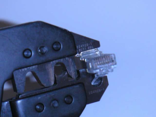
The old stranded-wire and solid-wire connectors are almost identical, but if you look at the crimping contacts with a magnifying glass, you will see one essential difference between them. The crimps of the stranded-wire connector have two teeth that bite straight down and through the insulation and conductors of each wire. But the solid-wire crimps have two teeth angles away from one another slightly, so that they bit down on either side of the solid conductor inside the wire. Both differ from the new connectors, which have no metal teeth at all.