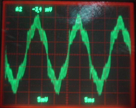
By mains hum we mean AC power hum, which is 50 Hz in Europe, and 60 Hz in North America. The following figure shows the mains hum we pick up with a 10-MΩ oscilloscope probe resting upon a wooden table in our laboratory in Boston. The amplitude of the signal is roughly 10 mV rms (root mean square), 15 mV in amplitude (average to peak), or 30 mVpp (peak to peak).
Our Subcutaneous Transmitters have a 10-MΩ input impedance, and they likewise pick up tens of millivolts of mains hum when we set them on a table. Biometric potentials such as EEG have baseline amplitudes measured in tens of microvolts. We would like to eliminate mains hum from our EEG recordings. In the following paragraphs, we measure the properties of mains hum, consider several physical mechanisms by which the signal can be induced in our electronic circuits, and conclude that mains hum is induced by electromagnetic waves radiated by the mains currents flowing in the electrical cables of our building.
We start by assuming that the source of mains hum can be modeled by an alternating-current (AC) voltage source, V, in series with an impedance, Z, which we call the source impedance. We are going to measure mains hum with an oscilloscope. We define our ground potential as the ground terminal of the oscilloscope probe. The voltage V induced on the probe will be a voltage with respect to ground.
We place the tip of our probe upon the metal frame beneath a wood-topped table. We do not connect the probe's ground terminal to the frame. Instead we clip the ground terminal to the insulation of the probe cable, so as to keep it isolated from the probe tip. With this arrangement, we see mains hum 2.2 Vpp.
Now we unclip the ground lead from the probe cable and touch it to the metal frame of the table, which is the same frame we are touching with the probe tip. The mains hum disappears. Its amplitude is less than 10 mV. When we touch the ground clip to the table, we are connecting Z directly to ground with a 0-Ω resistor, and all of V is dropped across Z. None is left for our probe to measure. When we do not touch the ground clip to the table, V is connected to Z in series with the impedance of our probe, which is 10-MΩ. We connect the ground clip to the table through a variety of resistors.
| R (MΩ) | V (mVpp) |
|---|---|
| 10 | 2200 |
| 5 | 1800 |
| 2 | 800 |
| 0.1 | 40 |
| 0.01 | <10 |
The voltage we see on the probe should be VR/(R+Z). Our measurements suggest that Z is of order 10 MΩ and V = 2 Vpp. We repeat the above experiment, but with the author's tongue in place of the table. We press the probe tip on the tongue and the end of a resistor as well. The other end of the resistor is connected to the probe ground. We observe a slight direct current (DC) voltage as well as our mains hum, which we include in the table.
| R (MΩ) | V (mVpp AC) | V (mV DC) |
|---|---|---|
| 10 | 100 | −500 |
| 5 | 100 | −500 |
| 2 | 80 | −250 |
| 0.1 | 20 | −100 |
| 0.01 | <10 | <10 |
From these measurements, we conclude that Z for mains hum on a human tongue with respect to the oscilloscope ground is of order 1 MΩ and V = 100 mVpp.
There are three ways that mains hum can be induced in a conducting object such as the metal frame of a table: magnetic induction, electrostatic induction, or reception of electromagnetic waves. That is to say: the object can act like the secondary coil of a transformer, the plate of a capacitor, or an antenna. The object can act like an antenna and pick up electromagnetic waves emitted by the current-carrying wires in the wall at greater distances.
We made a loop of wire 15 cm in diameter and connected it to our oscilloscope probe. One end we connected to ground and the other to the probe tip. The 15-cm loop picked up 4 mV of mains hum right next to a power supply, but ≤ 1 mV elsewhere. This is very much less than our probe picked up when disconnected. We made a 3-m diameter loop of wire. It picked up no more than the 15-cm loop. We see that the effect of connecting the loop to the probe is the same as connecting the probe ground and tip together. There is no significant magnetic pick-up of mains hum by a loop of wire.
Our Subcutaneous Transmitters (SCTs) presents a 10-MΩ input impedance across its two electrode leads. We place a A3013 transmitter on our table and take the fourier transform of eight-second intervals to obtain a sharp peak at 60 Hz, which is our mains hum signal in the US. The SCT picks up 1-30 mV depending upon its orientation and the arrangement of its leads. We place the transmitter in a Faraday Enclosures and mains hum drops to ≤10 μV.

Our faraday enclosure is made of steel fabric. It is too thin to block magnetic fields. But it blocks electrostatic fields and it reflects electromagnetic waves. The mains hum we observe in our laboratory must be due either to electrostatic fields or electromagnetic waves. It cannot be generated by magnetic fields.
Let us estimate the magnitude of the mains hum our table could pick up by electrostatic fields from the AC wires in the walls, floor, and ceiling of our laboratory. We model the table as a meter-square plate. Now suppose the wires in the wall act like another square-meter metal plate. This assumption greatly exaggerates the effective area and voltage of the wires, but we will find that even this exaggerated area and voltage is insufficient to explain our body's mains hum, so let us proceed with our exaggerated assumption.
Our body and the wires are separated by one meter. The capacitance of two plates of area one meter separated by one meter is 10 pF. The impedance of 10 pF at 60 Hz is 300 MΩ, which is much greater than the 10-MΩ source impedance of our table's mains hum. The actual area presented by the wires in the wall will be less than one hundredth of a square meter, so the actual source impedance of the mains hum induced by the electrostatic field will be tens of thousands of megaohms. This calculation suggests that it is impossible for mains hum to be caused by electrostatic fields.
We are left with only one possible source of mains hum: electromagnetic waves radiated by current-carrying wires that induce voltages in all conducting objects, including metal furniture, human bodies, and the wires of our SCTs. These waves are 60-Hz radio waves. Their wavelength is 6,000 km. A loop of wire attached to our oscilloscope probe is so much smaller than the wavelength that whatever voltage the incoming 60-Hz wave induces in one side of the loop should be canceled by an opposite voltage induced on the other side of the loop. And indeed we observe no mains hum pick-up with a loop of wire on our table-top. When we connect the tips of our SCT leads together, we make a loop antenna out of the leads, so 60-Hz waves would induce no mains hum. And indeed this is the case: connected EEG electrodes result in no mains hum on our table top. If we lay the two leads down so they are touching along their entire length, and they terminate next to one another but without touching, the 60-Hz waves should induce almost the same voltage in the two leads, so we should pick up a minimum of mains hum. And this is indeed the case: we get the least mains hum when the leads are close together and the same length. If we separate the two leads so they go off in different directions, the 60-Hz waves should induce different voltages in the leads, and we will see a maximum of mains hum. This is also the case: we see >30 mV mains hum only if the leads are separated.
Another property of 60-Hz electromagnetic waves is that they will be far-reaching, their power diminishing as the square of the distance from the current-carrying wires. And indeed: we see mains hum in the middle of our laboratory, even if we clear away all nearby electrical cords. Mains-hum radio waves permeate every building supplied with AC power, and the immediate surroundings of these buildings.
The power radiated by a current-carrying AC wire increases with current, so we expect to see mains hum amplitude fluctuating during the day as current consumptino changes within our building. This is also the case: when we record mains hum continuously with our SCTs, the power fluctuates with a combination of one-day and seven-day cycles.
Mains hum is caused by 50-Hz or 60-Hz radio-waves transmitted by power lines. We can shield our instruments from them with a faraday enclosure, or by implanting our instrument entirely within the same conducting body.