| Introduction |
| Versions |
| Assembly |
| Home-Made Enclosures |
| Development |
[06-MAR-26] What we call a Faraday enclosure is an enclosure designed to keep out and absorb 915-MHz microwave interference. Enclosures made with conducting walls are usually called Faraday cages, but we call them Faraday enclosures to avoid confusing them with animal cages. We recommend operating our telemetry system inside such enclosures so the system does not have to compete with ambient microwave interference. We strongly recommend operating our implantable stimulators inside such enclosures so that the bursts of microwave power we use to command the ISTs do not interfere with wireless devices outside the enclosure.
For conducting walls we use stainless steel mesh and aluminum sheet metal. Conducting walls alone are insufficient to make an effective Faraday enclosure. We need an absorber of microwaves inside the enclosure as well. All our enclosures are equipped with slabs of microwave absorbing foam. We must also provide some means for bringing signals in and out of the enclosure without compromising its isolation. We provide coaxial and ethernet feedthrough connectors in the back wall of our rigid enclosures. We provide coaxial and ethernet feedthrough assemblies for our canopy enclosures.

Our Faraday enclosures provide connected, conducting walls with one or more microwave-absorbing surfaces on the interior. Steel mesh allows light and air to enter and leave. Coaxial feedthroughs allow us to insert one or more antennas in the interior. Ethernet feedthroughs allow us to place Animal Cage Cameras (ACC) and Animal Location Trackers (ALT) in the enclosure. The enclosure not only reduces interference at the receiving antenna, but also stops our telemetry signals from interfering with any other system.
When our animal cages are stored on racks, we place the rack on a floor of aluminum sheet and cover the entire rack with a single canopy of stainless steel mesh. The canopy is supported by a frame made of aluminum tubes. We hang four 60-cm square absorbers from the frame inside the enclosure. We enter the canopy through one of two magnetically-sealed seams on either side of the front wall (see video). We bring coaxial antenna cables out of the enclosure by means of one or more Coaxial Feedthroughs (A3039E), which we tape to a convenient location on the edge of the floor. The bottom of the mesh wall fits between the interior and exterior cables. For Power over Ethernet (PoE) cables, we use an Ethernet Feedthrough (A3039D).

Our SCT signals are broad-band and low-power. The Subcutaneous Transmitter (A3028) transmits 300 μW in the 902−928 MHz Industrial Scientific Medical (ISM) band. These signals are easily swamped by interference. Without a Faraday enclosure, a mobile phone base station can disrupt reception from implanted SCTs at a range of 1500 m. With a Faraday enclosure, the same disruption will not occur unless the base station is 50 m away. A secondary benefit of our Faraday enclosures is to guarantee that no detectable signal from our transmitters emerges from your telemetry recording room. In North America, South America, and the UK, any device may use the 902-928 MHz band provided the device's peak power output is less than 1 W. In other countries, the 902-928 MHz band is licensed for amateur radio and radiolocation systems, and regulations prohibit our system from radiating intentionally within the band. The average 902-928 MHz power escaping a Faraday enclosures containing ten implanted SCTs is <10 nW. This power generates an electric field strength <60μV/m at range 10 m, which satisfies the ≤210 μV/m electromagnetic emission limit for unintentional radiators under regulations common to all nations.

One way to detect SCT signals is with a Damped Loop Antenna (A3015C) plugged into a Telemetry Control Box (TCB) or an Octal Data Receiver (ODR). Another is to place your animal cage on an Animal Location Tracker (ALT). Regardless of the detection mechanism, our Faraday enclosures provide a factor of one thousand attenuation of external microwave interference. In London, our enclosures provide robust reception on the top floor of a building, within a hundred meters of a mobile phone base station. But if we open an enclosure, reception is poor. In Edinburgh, on the top floor of one building, our enclosures were unable to provide robust reception within fifty meters of a set of three base stations. In another location in London, on the ground floor at the center of a brick building, we obtain perfect reception with no Faraday enclosure at all.

Before you select a location for your telemetry system, we recommend you the exact latitude and longitude of your location, and altitude, so that we can check the location of local mobile phone base stations. If there are any within one hundred meters, facing directly towards you, and you are high enough off the ground to be directly in their line of transmission, we will advise you on measurements you can make of the interference power so as to determine whether your preferred space can support our SCT system. Rural locations have far less interference. In one rural setting we were able to receive SCT signals at a range of four meters with no Faraday enclosure. Aquatic settings also permit us to operate the SCT system without a metallic Faraday enclosure. The water itself reflects and attenuates external interference, creating an aquatic enclosure, so that we are able to operate in an urban location with four antennas immersed in the aquarium.
[06-FEB-26] We have two Faraday enclosures in active production: the FE3B and the FE5B. Both of these enclosures we can ship in a wooden crate to any country in the world by air freight. The FE3B will arrive fully-assembled. The FE5B will arrive as a kit. The table below lists these and earlier versions that we no longer manufacture. Starting in March 2024, we ship all our enclosures fully-assembled in a wooden crate, like this.
| Part | Height (cm) |
Depth (cm) |
Width (cm) |
Number of Cages |
Number of Antennas |
Description | Status |
|---|---|---|---|---|---|---|---|
| FE3A | 60 | 65 | 91 | 3 | 2 | bench-top, stackable | Discontinued |
| FE3AS | 60 | 65 | 91 | 6 | 4 | bench-top, stackable, with shelf | Discontinued |
| FE3B | 60 | 65 | 91 | 6 | 4 | bench-top, stackable, easy-replace mesh | Active |
| FE3B-ACC2 | 60 | 65 | 91 | 6 | 4 | as FE3B, with two cameras mounted in roof. | Active |
| FE3BS | 60 | 65 | 91 | 6 | 4 | bench-top, stackable, easy-replace mesh, with shelf | Active |
| FE5A | 208 | 76 | 163 | 40 | 8 | free-standing steel mesh canopy with aluminum floor | Discontinued |
| FE5B | 208 | 76 | 160 | 40 | 8 | free-standing steel mesh canopy with aluminumu floor. | Active |
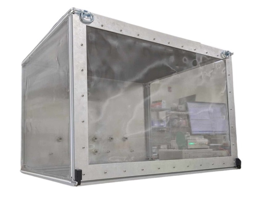
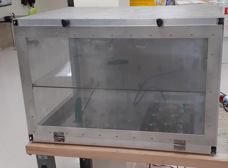
The FE3B is a rigid-frame enclosure that will house two large rat cages with space for cameras mounted above. The FE3B-ACC2 is an FE3B with two Animal Cage Cameras (ACC) mounted ready-to use in the foam of the roof. The front wall is a door that swings down, giving access to the entire interior space. Electrical power and signals pass through the back wall by means of coaxial and network feedthrough connectors. The FE3BS is an FE3B with a shelf installed, which permits us to load six mouse cages in one enclosure: three on the floor and three on the shelf. All versions of the FE3B comes with top-side handles for carrying it about, but if we remove these handles, we can stack several FE3BS on top of one another. We could, for example, assemble a mobile recording unit for twenty-four mouse cages by stacking four FE3BS on a wheeled platform. Note that the interior width and depth of the aluminum frame enclosures are 1 cm smaller on account of the thickness of the aluminum brackets. The interior height is 6 cm shorter because of the foam absorber on the underside of the lid. The opening at the top of the enclosure is roughly 90 mm smaller on account of the width of the aluminum brackets.

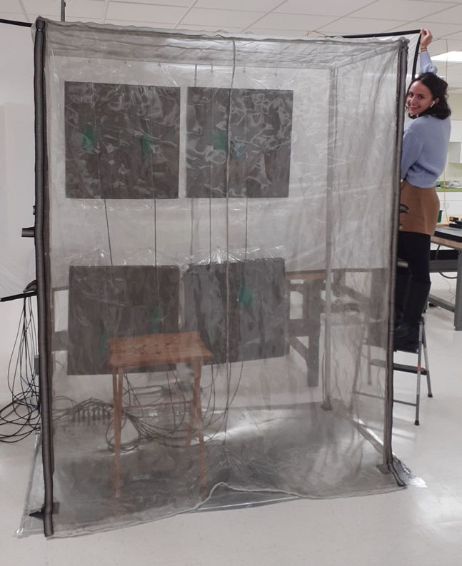
The FE5B is a soft-walled canopy held up by a rigid frame. This canopy can enclose an IVC (Individually-Ventilated Cage) rack, a two-meter tall set of shelvs holding dozens of animal cages, or a bench-sized experimental station. The canopy's microwave absorbers hang on the back or side walls, wrapped in vinyl. Magnetically-closed seams on the left and right allow us to open the front wall and service the cages, or roll the IVC rack out of the enclosure for cleaning. Electrical power and signals pass beneath the enclosure's back wall by means of Coaxial Canopy Feedthroughs A3039E, in the case of telemetry antenna signals, and Ethernet Canopy Feethroughs A3039F, in the case of Power over Ethernet connections.
| Part | Name | Description |
|---|---|---|
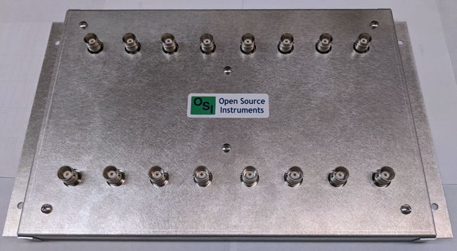
| A3039E | Eight-Way Coaxial Feedthrough | Brings eight antenna cables into a canopy enclosure. |
| A3039F | Eight-Way Ethernet Feedthrough | Brings eight Ethernet cables into a canopy enclosure. |
| MA3 | Microwave Absorber, 61 cm × 61 cm × 6 cm | For hanging on back wall of canopy enclosure. |
| MF3 | Microwave Absorbing Foam, 61 cm × 61 cm × 6 cm | For gluing to the ceiling of a benchtop enclosure. |
| SM44 | Stainless Steel Mesh Fabric, 1.2 m × 1.2 m | For making transparent walls and windows. |
Faraday enclosures that are effective at our 915-MHz microwave frequencies are hard to build. We must use grounded feedthroughs for all electrical connections. We must include microwave absorbers inside the enclosure. We must make sure there are no slits for microwaves to pass through. Once you have one of our Faraday enclosures in your laboratory, however, it becomes possible to copy the enclosure construction and make your own enclosures, should you be inclined to do so. In order to support our customers in the construction of their own Faraday enclosures, we sell various accessories to construction that are necessary to ensure that such home-made enclosures are effective. The table above lists feedthroughs, absorbers, and stainless steel mesh that you can purchase from us to use in your own construction.
[01-JUN-26] We ship our bench-top Faraday enclosures fully-assembled in wooden crates, like this. We ship our Faraday canopies disassembled in wooden crates. The crates arrive on a truck and are transferred to your receiving dock. At that point, you can either have the crate moved up to your laboratory, or you can open the crate on the dock. To open the crate, you must release the metal latches that hold it together, as we demonstrate in this movie. With the crate open, remove the fully-assembled enclosure or the disassembled canopy. The enclosures are equipped with handles, making it easy for two people to carry the enclosure to your laboroatory.
| Part | Documents | Details |
|---|---|---|
| FE3A | mechanical drawings, assembly drawing, parts list. | Discontinued |
| FE3AS | mechanical drawings, assembly drawing, parts list. | Discontinued |
| FE3B | mechanical drawings, assembly drawing, assembly guide. | Ships fully-assembled |
| FE3B-ACC2 | construction photograph. | Ships fully-assembled |
| FE3BS | mechanical drawings, assembly drawing, assembly guide. | Ships fully-assembled |
| FE5A | assembly guide. | Discontinued |
| FE5B | assembly drawing, assembly guide. | Requires assembly. |
The FE5B we ship as a set of struts, joints, absorbers, cable ties, floor plates, aluminum tape, and the stainless steel mesh canopy. The components have even dimensions in inches, where one inch = 1" = 2.54 cm. The struts are 1" square aluminum tubes. The frame consists of eight struts 40" long, two struts 61" long, two struts 28" long, four corner joints, four straight joints, and four feet. We make each of the four vertical legs of the frame by connecting two 40" struts together. The horizontal struts are all single pieces. The outer dimensions of the frame are 82" high, 63" wide, and 30" deep. The inner dimensions are 81" x 61" x 28" deep when we take account of the width of the struts. The base of the enclosure consists of three 36" x 24" aluminum sheets, 1/16" thick. These we tape to the floor next to one another to make a conducting surface 36" x 72". We assemble the frame and place it upon the base. We drape the canopy over the frame. We screw the canopy edges to the front vertical struts. To complete the assembly, we need a hammer and a power screwdriver with a phillips bit. The FE5B is identical to the FE5A, except is one inch narrower. This one inch reduction in width allows us to pack the FE5B in the same size crate we use for our FE3B. Our pictorial FE5B Assembly Guide shows each step of the assembly process. The video below shows how to screw the canopy to the front struts.

When we enclose an IVC rack in a Faraday Canopy, we must accommodate the inlet and outlet air ventilation pipes. We must not place any electrical machinery inside the Faraday enclosure other than antennas and Power over Ethernet devices that we have tested for compatibility with our telemetry system. We must leave the ventilation pumps outside and run the air in and out of the enclosure with non-conducting, plastic pipes that pass through the enclosure walls. To make an opening for a pipe, we make a cross-cut in the sides of the canopy to allow each ventilation pipes to enter. The cross-cuts are slightly bigger than the pipes, so that each will provide four triangles of steel mesh fabric that you can tape around the pipe outside the enclosure using aluminum tape. These holes will compromise the isolation of the enclosure, but the enclosure will still be effective enough to ensure reliable telemetry reception.
[06-FEB-26] Some of our customers prefer to make their own Faraday enclosures, which we call home-made enclosures. Home-made enclosures usually work well enough, but sometimes they don't. If you have your own machine shop, for which labor is already paid for, you may save money making your own enclosures, especially when you consider the cost of shipping a fully-assembled enclosure from our facility to your institute. But the construction of an effective 915-MHz Faraday enclosure is non-trivial. The most common problems with home-made enclosures are the omission of the microwave absorbing foam, failure to bring all electrical connections into the enclosure with grounded bulkhead feedthrough connectors, and failure to provide an adequate seal around the door. If you are determined to make your own enclosures, we can provide you with microwave absorbing foam, stainless steel mesh fabric, feedthrough connectors, and advice on the details of your design. But we will insist that you purchase at least one Faraday enclosure from us, so that you will have one of our proven enclosures to compare with your own. If you have problems with reception, the presence of an OSI-made enclosure will permit us to determine if the problems arise from a defect in your home-made enclosure or from some other component in the data acquisition system.

The simplest enclosure to manufacture is one with a lid we can remove. We made our first enclosures out of aluminum angle-brackets, epoxy, and stainless steel mesh. Instructions for making these inexpensive, top-loading enclosures are in our FE2 Assembly manual. Enclosures with hinged front doors are more difficult to manufacture, because it is harder to make sure there is no gap around the edge of the door through which microwaves can penetrate. But enclosures with front doors have the great advantage that they can be stacked one upon the other, as shown below.

An easier door to assemble is a sliding door, such as in the FE2D designed and build by a customer in Germany. A sliding door gives good isolation provided it is equipped with conducting foam gaskets around the edges, as shown in this close-up of the FE2D door corner.
[02-JAN-25] For a chronological account of our efforts to design effective 915-MHz Faraday enclosures, see our separate Development and Production page.