 A3036 Implantable Light-Emitting Diode Manual
© 2019-2026 Kevan Hashemi, Open Source Instruments Inc.© 2021 Alice Hashemi, Open Source Instruments Inc.
| Description |
| Versions |
| Optical Power |
| Heating |
| Design |
Note: The A3036IL Implantable Light-Emitting Diode (ILED) is an active product, but its partner device of the same assembly number, the A3036 Implantable Stimulator-Transponder, has been replaced by the A3041 Implantable Stimulator-Transponder.
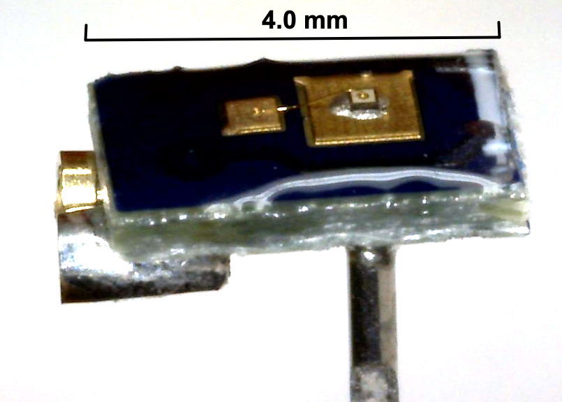
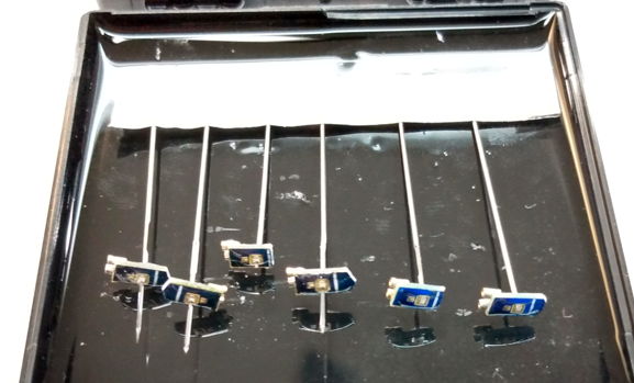
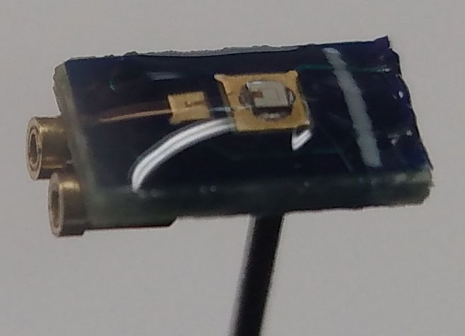
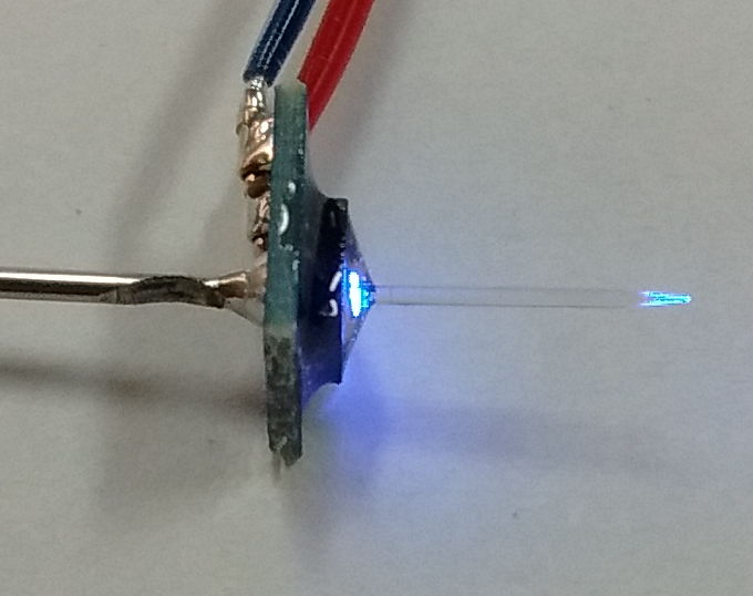
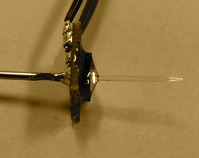
[20-APR-26] Our A3036IL Implantable Light-Emitting Diodes (ILEDs) are light-emitting diodes (LEDs) designed for implantation in animals. They provide the stimulation for optogenetic experiments. They are accessories to our A3041 Implantable Stimulator-Transponders (ISTs). The A3036IL uses a variety of LEDs: the blue and green EZ500, blue and green EZ290, and deep red LXZ1-PA01. All A3036ILs are equipped with a thin-walled steel tube on the far side from the LED to allow the ILED to be mounted during implantation. The tube is partially cut away near the base so it may be cut more easily after the ILED has been secured with dental cement. Our ILEDs come in three classes: Clear-Epoxy LED (CE-LED), Tapered-Fiber LED (TF-LED), and Blunt-Fiber LED (BF-LED). Each class is named after the element that delivers light to the target tissue.
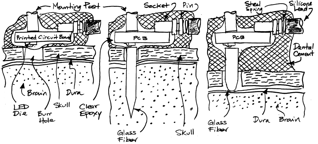
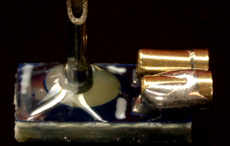
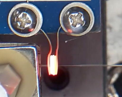
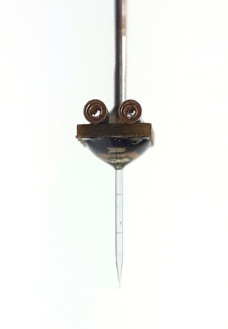
All our ILEDs are built on a circuit board. The LED is on the "bottom" side. The connection sockets and mounting post are on the "top" side. Clear epoxy surrounds the base of the mounting post and the LED. In a CE-LED, the entire LED die and bond wire is covered in clear epoxy. In the TF-LED and BF-LED, the base of the fiber is pressed up against the LED die, but there is a thin layer of clear epoxy between the two, and clear epoxy surrounds the LED die, bond wire, and fiber base, holding the fiber in place. When we mount an ILED on the skull of an animal, we use the mounting post to position the ILED. We connect the lamp power pins from our implantable stimulator to the two sockets. We cover the ILED with dental cement so as to fasten it in place on the skull. To ensure a strong bond, we can include nearby a screw threaded into the skull that we embed in the same dental cement. We take care to surround the lamp power sockets and pins on all sides with cement so as to insulate them from the rest of the animal's body: when we turn on the ILED, we do not want to see artifact in our recordings of other biopotentials. Once our first application of cement is cured, we cut the mounting post, then cover the exposed cut tube with a little more cement.
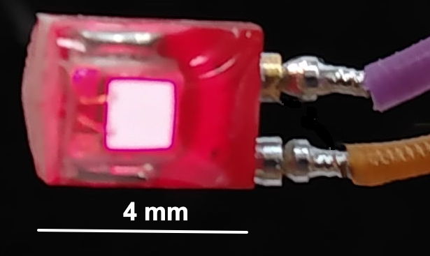
The A3036IL Clear-Epoxy Implantable Light-Emitting Diode (CE-LED) is designed for non-intrusive illumination of body tissue. We attach it to the surface of the organ we wish to illuminate. If we want to illuminate brain tissue with a CE-LED, we can attach the CE-LED to the surface of the skull and hope to illuminate the brain through the thickness of the skull. But the dispersion of light in bone tissue causes a dramatic reduction in light intensity. We may be able to illuminate the brain through the 300-μm thickness of a mouse's skull, but we are going to need a lot of power to provoke optogenetic response through the 1-mm thickness of a rat's skull. In the case of a rat, we can make an aperture in the skull and set the CE-LED within the aperture to illuminate the brain surface directly without penetrating the dura.
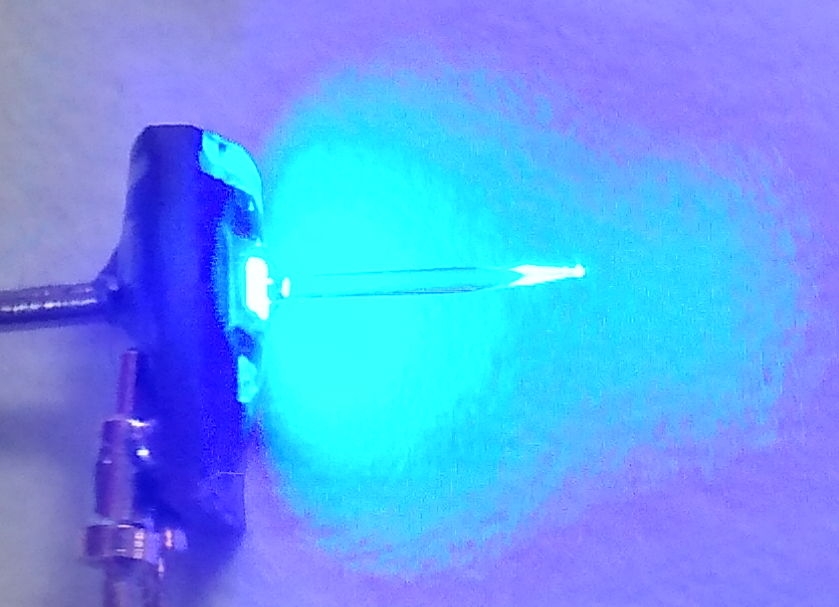
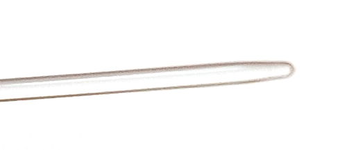
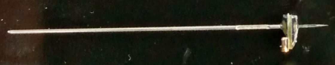
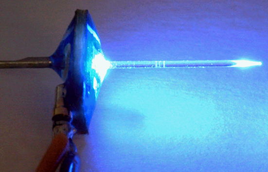
Our A3036IL Tapered-Fiber LEDs (TF-LEDs) are designed to deliver light deeper into body with the highest possible intensity at the target location. The sharp tip of the TF-LED serves two purposes: it minimizes damage to the tissue the fiber passes through to arrive at its target, and it provides light emission a hemisphere rather than in a downward cone. The Blunt-Fiber LED (BF-LED) is designed to carry light through a burr hole to the surface of the skull in cases where we do not want to penetrate the dura or the brain surface. The BF-LED delivers a higher intensity of light to the brain surface than a CE-LED, and does not require such a large aperture to accommodate the LED. Furthermore, the BF-LED allows us to place cement below the ILED circuit board and all around the power sockets and pins with more ease, thus providing better insulation of the lamp power from the body, and minimizing lamp artifact in our recorded biopotentials.
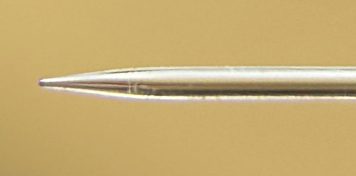
The glass optical fibers we use with our A3036IL Implantable Light-Emitting Diodes are made of high index glass to capture the maximum possible light from the LED die. The fibers are polished at the base and tapered at the tip. The taper allows the fiber to penetrate to the target area with the minimum of trauma to the surrounding tissue. The taper also has the advantage of emitting light in all directions, as opposed to only downwards. We glue the polished base to the surface of an LED and the fiber carries LED light to the tapered tip. We call the combination of fiber and LED a Tapered-Fiber LEDs (TF-LEDs). The fraction of optical power emitted by the LED that is delivered to the tapered tip of the fiber is the coupling efficiency of the fiber. Our TF-LEDs have a typical coupling efficiency of around 38%.
We make A3036IL TF-LEDs out of bare LED chips wire-bonded to a printed circuit board. We have blue and green TF-LEDs, but we have not yet found a red LED of adequate efficiency that we can purchase in die form for contact coupling with the fiber base.
The A3036IL Clear-Epoxy Implantable Light-Emitting Diode (CE-LED) has the LED die covered with clear epoxy. We can place it on the surface of an organ or the skull. We can also drill a hole in the skull and place the CE-LED over the hole, as shown in the sketch above. We do not use a mold or a die to cast the clear epoxy on the CE-LED. Instead, we coat the LED die with epoxy and spread the epoxy around under a microscope so that the die is covered by no more than half a millimeter of epoxy. The resulting epoxy encapsulation is flat to ±0.2 mm, but usually has a slight dome shape. We make red, blue, and green CE-LEDs.
[26-MAY-26] The following versions of the Implantable Light-Emitting Diode (A3036IL, ILED) are in production. The gold-plated pins on the end of the stimulator's leads mate with a pair of sockets on the A3036IL. We use attached and wire-bonded EZ500 chips for our blue and green CE-LEDs, TF-LEDs, and BF-LEDs. We use the deep-red Luxeon Z series LXZ1-PA01 for our red CE-LEDs. We do not make red fiber-coupled LEDs. Our ILED part numbers begin with the "A3036IL", where "3036" is the OSI assembly number and "IL" is for "Implantable Lamp". This is followed by a dash and a letter. If the letter is solitary, the ILED is a CE-LED, which is an LED in clear epoxy with a mounting post and two sockets. The letter tells us which LED the ILED contains: "A" for blue EZ500, "B" for green EZ5600, and "E" for red Luxeon Z. The number after the letter indicates a fiber, and gives the fiber diameter in microns. Another dash is followed by the length of the fiber in millimeters. The length is followed by a letter "T" for a tapered fiber and "B" for a blunt fiber.
| Version | Type | LED | Light Guide Dia, Len, Tip |
Wavelength (nm) |
Die Size (μm × μm) |
Optical Power (mW at 10 mA) |
|---|---|---|---|---|---|---|
| A3036IL-A | CE-LED | Blue EZ500 | Epoxy Dome | 460 | 480 × 480 | 10.3 |
| A3036IL-B | CE-LED | Green EZ500 | Epoxy Dome | 527 | 480 × 480 | 7.2 |
| A3036IL-A270-4T | TF-LED | Blue EZ500 | 270 μm, 4 mm, Taper | 460 | 480 × 480 | 2.8 |
| A3036IL-B270-4T | TF-LED | Green EZ500 | 270 μm, 4 mm, Taper | 527 | 480 × 480 | 1.8 |
| A3036IL-A270-6T | TF-LED | Blue EZ500 | 270 μm, 6 mm, Taper | 460 | 480 × 480 | 2.8 |
| A3036IL-B270-6T | TF-LED | Green EZ500 | 270 μm, 6 mm, Taper | 527 | 480 × 480 | 1.8 |
| A3036IL-A450-4B | BF-LED | Blue EZ500 | 450 μm, 4 mm, Blunt | 460 | 480 × 480 | 3.3 |
| A3036IL-A450-8T | TF-LED | Blue EZ500 | 450 μm, 8 mm, Taper | 460 | 480 × 480 | 3.3 |
| A3036IL-B450-8T | TF-LED | Green EZ500 | 450 μm, 8 mm, Taper | 527 | 480 × 480 | 2.4 |
| A3036IL-E | CE-LED | LXZ1-PA01 | Epoxy Dome | 650 | 1000 × 1000 | 8.0 |
We have high-index fiber in stock of all diameters 270 μm to 450 μm. We can make blunt or tapered-tip fibers of any diameter in this range. The shortest fiber we can make easily is 4 mm. For an additional charge, we can reduce the length to 3 mm.
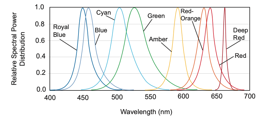
The EZ500 data sheet does not provide spectra for light emission. But the Luxeon Z data sheet from Philips Lumileds provide spectra. If we assume the EZ500 blue and green spectra are similar, the half-power spectral width of the EZ500 460-nm blue LED is 20 nm, and of the 525-nm green is 50 nm.
[26-MAY-26] The following table compares the optical power output of at 10 mA forward current for various combinations of fibers, domes, and LEDs. For all these devices, optical power is approximately linear with current. Notice that the EZ290 fiber-coupled LEDs are not as efficient as the EZ500, even though the surface area of the EZ290 is smaller. The central bond wire of the EZ290 interferes with the contact between the fiber and the emitting surface, forcing us to keep the base of the fiber farther from the die, and shadowing a portion of the die as well.
| Version | Type | LED | Light Guide Dia, Len, Tip |
Wavelength (nm) |
Die Size (μm × μm) |
Output (mW at 10 mA) |
|---|---|---|---|---|---|---|
| A3036IL-A | CE-LED | Blue EZ500 | Epoxy | 460 | 480 × 480 | 10.3 |
| A3036IL-B | CE-LED | Green EZ500 | Epoxy | 527 | 480 × 480 | 7.2 |
| A3036IL-A270-4T | TF-LED | Blue EZ500 | 270 μm, 4 mm, Taper | 460 | 480 × 480 | 2.8 |
| A3036IL-B270-4T | TF-LED | Green EZ500 | 270 μm, 4 mm, Taper | 527 | 480 × 480 | 1.8 |
| A3036IL-A270-6T | TF-LED | Blue EZ500 | 270 μm, 6 mm, Taper | 460 | 480 × 480 | 2.8 |
| A3036IL-B270-6T | TF-LED | Green EZ500 | 270 μm, 6 mm, Taper | 527 | 480 × 480 | 1.8 |
| A3036IL-A450-4B | BF-LED | Blue EZ500 | 450 μm, 4 mm, Blunt | 460 | 480 × 480 | 3.3 |
| A3036IL-A450-8T | TF-LED | Blue EZ500 | 450 μm, 8 mm, Taper | 460 | 480 × 480 | 3.3 |
| A3036IL-B450-8T | TF-LED | Green EZ500 | 450 μm, 8 mm, Taper | 527 | 480 × 480 | 2.4 |
| A3036IL-C | CE-LED | Blue EZ290 | Epoxy | 460 | 290 × 290 | 7.4 |
| A3036IL-D | CE-LED | Green EZ290 | Epoxy | 527 | 290 × 290 | 3.9 |
| A3036IL-C450-8T | TF-LED | Blue EZ290 | 450 μm, 6 mm, Taper | 460 | 290 × 290 | 3.8 |
| A3036IL-D450-8T | TF-LED | Green EZ290 | 450 μm, 8 mm, Taper | 527 | 290 × 290 | 2.0 |
| A3036IL-C270-6T | TF-LED | Blue EZ290 | 270 μm, 6 mm, Taper | 460 | 290 × 290 | 1.8 |
| A3036IL-D270-6T | TF-LED | Green EZ290 | 270 μm, 6 mm, Taper | 527 | 290 × 290 | 1.0 |
| A3036IL-E | CE-LED | Red LuxeonZ | Epoxy | 650 | 1000 × 1000 | 8.0 |
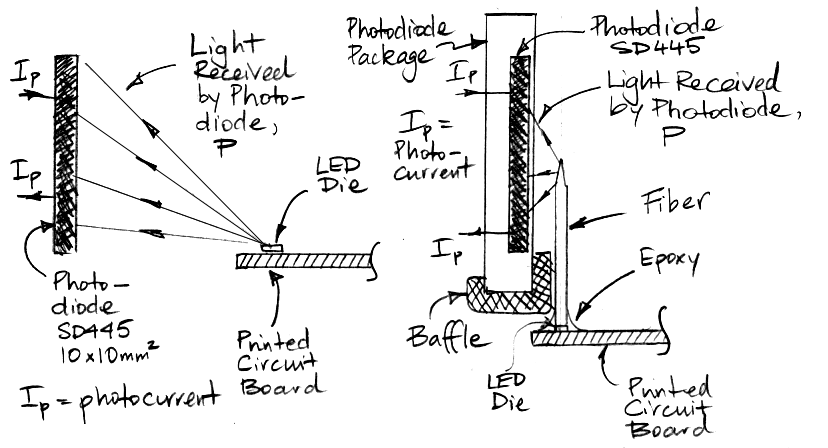
We calibrate our implantable LEDs by measuring their optical power output when the forward current is 10 mA. We measure the LED's power output with one of our calibration stands. We have one calibration stand for bare LEDs and another for fiber-coupled LEDs. In our bare LED calibration stand, we have a 10-mm square SD445 photodiode off to one side, while the bare LED emits vertically. A small fractioni of the light from the LED lands upon the photodiode, but we measure this fraction with sufficient accuracy to calibrate our bare LED output power to ±5%. In our fiber-coupled LED calibration stand, we use the same type of photodiode to measure the power emitted only by the tip of the fiber. A baffle obscures the base of the fiber from the photodiode. In this case, a larger fraction of the light from the fiber tip is incident upon the photodiode, but some of it is reflected at the photodiod surface. We measure the fraction of light collected with sufficient accuracy to allow us to measure the power output of blunt and tapered fibers to ±5%.
The LED output power is approximately proportional to current, as shown in the plot below. We get roughly twice as much power at 20 mA and half as much at 5 mA.The LED we prefer for fiber-coupling is the EZ500, which comes in both blue and green, but no other colors. The EZ500 light-emitting surface is 480 μm square, with a bond wire to one side, so that we can lower the base of an optical fiber right onto the emitting surface for greater coupling efficiency. For red light, we use the LXZ1-PA01 from the Luxeon Z family, which provides a 1-mm square emitting surface. The LXZ1-PA01 is an efficient source of 650-nm deep-red light for illuminating the surface of organ tissue. But its emitting surface is too large for efficient coupling of light into an optical fiber.
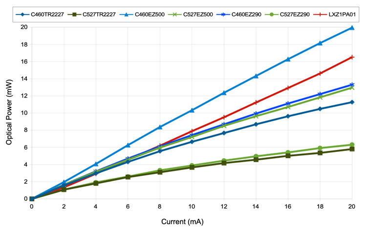
The blue EZ500 produces roughly 1 mW/mA, or one milliwatt of optical power per milliamp forward current. The green EZ500 produces roughly 0.5 mW/mA. The deep red LXZ1-PA01 produces roughly 0.8 mW/mA. We can make Clear-Epoxy LEDs (CE-LEDs) out of all of these LEDs, so we can provide surface illumination of tissue in blue, green, or red. The A3036IL-A, for example, is a blue CD-LED made with a C460EZ500 LED covered in clear epoxy. Another type of surface illuminator is the Blunt-Fiber LED (BF-LED). These are designed to transport light through the sull to the surface of the brain, which they do not penetrate. We can construct BF-LEDs only in blue and green. The red LXZ1-PA01 surface is too large for fiber coupling, and is furthermore covered with a layer of silicone that prevents secure binding of the fiber to the LED package.
We make depth illuminators by gluing a glass fiber with a tapered tip to a LED and inserting the tapered tip to the required depth in the brain. We call these Tapered-Fiber LEDs (TF-LEDs). Roughly one third of the light emitted by the LED is captured by the polished, flat base of the fiber and transported to its tapered tip, where it radiates in all directions. We make the tapered fibers by polishing one end of a high-index optical fiber, and tapering the other end with the help of our tapermaking machine. The A3036IL-A270-4T is a blue C460EZ500 with a 4-mm long, 270-μm diameter fiber light guide with a tapered tip. The A3036IL-A270-4T's average power output at the fiber tip is 2.8 mW for 10 mA forward current.
We measure optical power using an SD445 photodiode and an ammeter. We convert photocurrent into optical power using 0.18 mA/mW for 460-nm blue, 0.25 mA/mW for 527-nm green, and 0.40 mA/mW for 655-nm red light. We have two calibration stands that permit us to make consistent measurements of power for any combination of LED and fiber. The drawing below shows the arrangement of LED or TF-LED and photodiode in each stand. For more information on the calibration and appearance of the test stands, see our development notes.

When we cap an LED with epoxy, we make sure the surface is convex. We avoid loss by total internal reflection within the epoxy, and we direct the light more in the forward direction, which favors illumination of a surface directly in front of the ILED. But the epoxy dome is never uniform, so measuring the power emitted by the ILED after application of the epoxy dome is difficult. We assume the total power transmitted by the ILED is equal to the total power emitted by the LED die before we apply the dome.
In the case of fiber-coupled ILEDs, the fraction of the power emitted by the LED that reaches the fiber tip depends upon the area of the fiber and the area of the LED die, as well as the numerical aperture of the fiber itself. We make our light guides out of optical fiber with numerical aperture 0.86 (core index 1.72, cladding index 1.49). All light within ±60° of the fiber axis will be captured by the fiber and transported to the tip. For a typical LED, this ±60° accounts for 75% of the light emitted. A 450-μm diameter light guide, perfectly polished at the base, and perfectly positioned on a 480-μm square EZ500 LED will couple 51% of the emitted light to the fiber tip. The A3036IL-A450-8T uses a 450-μm fiber on a C460EZ500, and we obtain coupling efficiency of around 40%.
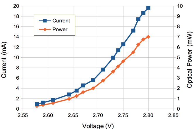
The Implantable Stimulator-Transponder (A3041B) boosts its battery voltage to a fixed 3.3 V or 5.0 V. It also provides a current limit we can apply to the stimulus. When equipped with 45 mm long leads, each will have resistance 28 Ω, making a total of 56 Ω. Suppose we turn up the stimulus current to its maximum value of 10 mA. To determine the actual LED current we need to know the approximate forward voltage drop of the LED at 10 mA. The A3036IL-A450-8T TF-LED has forward voltage 2.73 V at current 10 mA. The voltage drop across 56 Ω at 10 mA is 0.56 V. Thus 3.29 V is enough to drive 10 mA through the leads and LED. At this current, the tip of the fiber produces 5 mW. Thus the maximum optical power from the TF-LED when driven by the A3041B is 5 mW.
[27-MAY-26] All but the smallest of our A3041 Implantable Stimulator-Transponders, when connected to an A3036 Implantable Light Emitting Diode (ILED), are capable of overheating the brain. For a discussion of heat generation by ILEDs and its rate of dissipation in the brain, see the Heating chapter of our Implantable Stimulator Overview.
[09-JUN-25] For design files and development logbook, see the A3036 design and development page at D3036.