| Description |
| Versions |
| Connector |
| Surgery |
| Old Versions |
| Design |
NOTE: As of 10-OCT-25, we are replacing salmon leads with purple leads in all Electrode Interface Fixtures (EIFs).
NOTE: As of 10-OCT-25, we are replacing our original Electrode Interface Fixture (EIF) part-numbering system with a one that specifies the length, type, and termination of each lead individually.
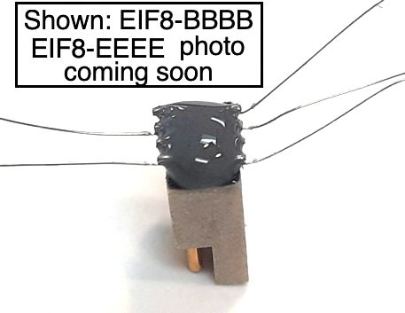
[01-JUN-26] The Electrode Interface Fixture (EIF) mounts permanently on the skull of a subject animal. The EIF mates with a Head-Mounting Transmitter (HMT) such as the Head-Mounting Transmitter (A3040). It provides two or more electrical connections between the HMT and animal biopotentials, most often intracranial electroencephalogram (iEEG). Each connection is terminated with an electrode chosen from our Electrode Catalog. The connections themselves are wires chosen from those we have found to be compatible with the EIF surgical procedure.
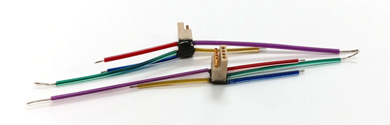
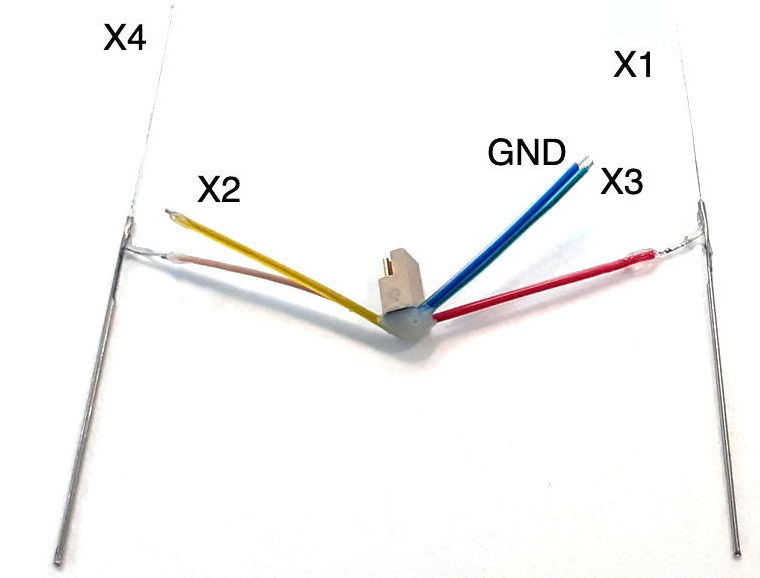
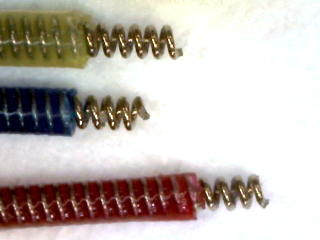
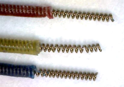
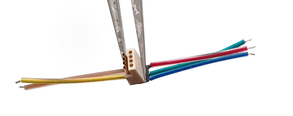
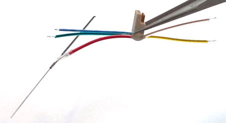
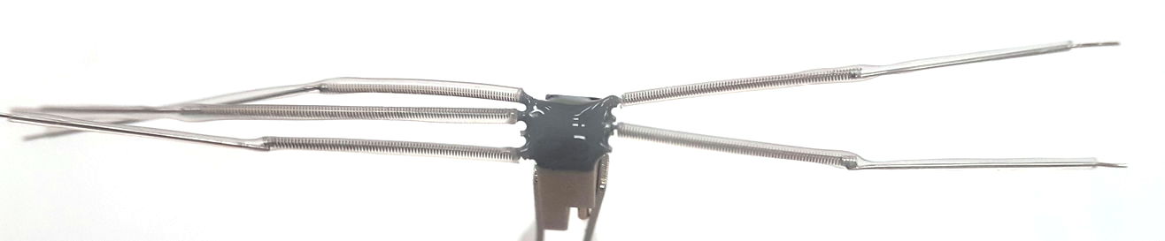
Our EIF part numbers are long and cumbersome, but they have the great advantage of being specific. The EIF8-C10A-C10A-C18P-C22P-C10A shown above consists of an eight-way connector with five silicone-insulated spring leads. The lead lengths for X1, X2, X3, X4, and GND are 10, 10, 18, 22, and 10 mm respectively. The terminations are bare coils of length 1, 1, 3, 3, and 1 mm respectively, as indicated by the letters A, A, P, P, and A in the part number. The EIF8-C15X-C15A-C15A-C15X-C15A shown below is equipped with five 15-mm silicone-insulated spring leads, two of which are terminated with X-Electrodes.
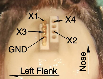
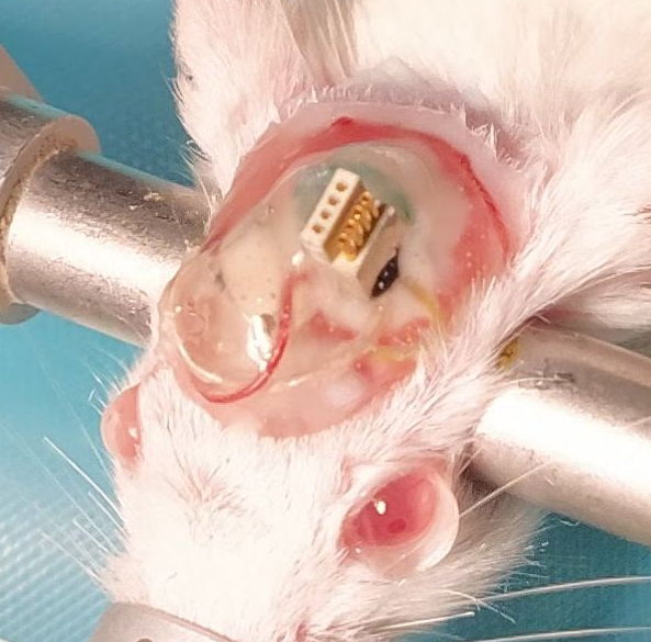
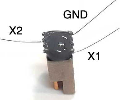
When we mount the EIF on the head of an animal, we must be sure to orient its connector correctly with respect to the center-line of the animal's body. We want the antenna of the HMT that mounts on the EIF to extend behind the animal's head, so that it hovers over the animal's back. If we put the EIF on the wrong way around, the antenna will stick out over the animal's nose. We have not tried mounting antennas over a mouse's nose, but our assumption has always been that an antenna in front of the mouse's nose, within easy reach of both its hands would be a bad idea.
We can equip the EIF8 with a variety of leads, and we can cut each lead to a specified length with ±1 mm precision. For step-by-step surgery instructions, see our Surgical Protocols page. For a discussion of the principles of EIF surgery, see the Surgery chapter of this manual. For a discussion of the principles of mounting and unmounting HMTs, see the Mount and Unmount chapter of the HMT manual.
[04-FEB-26] There are many possible configurations of the EIF. In principle, each configuration can be described using our EIF part-numbering scheme. Once someone has ordered a particular configuration, it graduates from being a mere "configuration" to a "version". The minimum order quantity for any particular version is ten pieces. Each EIF consists of a connector and a number of wires leading from the connector. Each wire has a lead type, a lead length, and a lead termination. The EIF8 is built around an eight-pin connector, which we equip with between two and five leads. The EIF8 part number consists of five lead specifications one after another, separated by dashes. These five leads are connected to X1, X2, X3, X4, and GND respectively, which are pins P-7, P-4, P-3, P-8, and P-1 on the connector respectively. We specify each lead with a lead letter code, a length in millimeters, and a termination letter code. If there is no lead present for one of these pins, we use a solitary "0" for the pin's lead specification.
| Letter | Name | Description |
|---|---|---|
| C | C-Lead | 316SS, coil of 50-μm wire, colored silicone, 500 μm OD. |
| K | K-Lead | 316SS, annealed, 75-μm wire, clear teflon, 140 μm OD. |
| L | L-Lead | 316SS, annealed, 125-μm wire, clear teflon, 200 μm OD. |
| J | J-Lead | 316SS, annealed, 125-μm wire, colored silicone, 350 μm OD. |
Our lead table includes our flexible, silicone-insulated, 0.5-mm diameter C-Leads, but does not include the larger B-Leads that are available for our Subcutaneous Transmitters (SCTs). The B-Leads are not suitable for the tight quarters of the EIF surgery procedure. They are 0.7-mm in diameter and significantly less flexible than the C-Leds.
| Letter | Name | Description |
|---|---|---|
| A | A-Coil | Coil, 316SS, length 1 mm. |
| P | P-Coil | Coil 316SS, length 3.0 mm. |
| F | F-Cut | Flush cut end to insulated lead. |
| X | X-Electrode | Depth electrode, wire 125-μm dia 316SS, insulation 200-μm dia teflon. |
| Y | Y-Electrode | Depth electrode, wire 75-μm dia 316SS, insulation 140-μm dia teflon. |
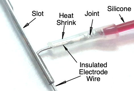
When we connect our flexible, coiled steel leads to depth electrodes, we insulate the joints between the coiled leads and the solid steel wire of the X-Electrode with flexible heat shrink. We use the smallest diameter heat shrink that will fit over the larger of the two leads we are joining. We are unable to buy all diameters of heat shrink in both transparent and black, so sometimes this heat shrink is transparent, and sometimes it is black.
The table below provides some example part numbers. All EIF8 fixtures are build around the PZN-08-VV connector from Omnetics, see drawing A79614.
| Part Number | Description |
|---|---|
| EIF8-C10X-C10A-C10A-C10A-C10A | Five C-Leads, all 10 mm long. Terminated either with an X-Electrode for X1 and an A-Coil for all X2, X3, X4, and GND. |
| EIF8-K10F-K10F-0-0-K10F | Three 10-mm leads for X1, X2, and GND. Leads are 75-μm stainless steel with 140-μm diameter teflon insulation. No leads for X3 or X4. |
| EIF8-C20X-0-0-0-C10A | Two C-Leads. The X1 lead is 20 mm long and terminated with an X-Electrode. The GND lead is 10 mm long and terminated with an A-Coil. |
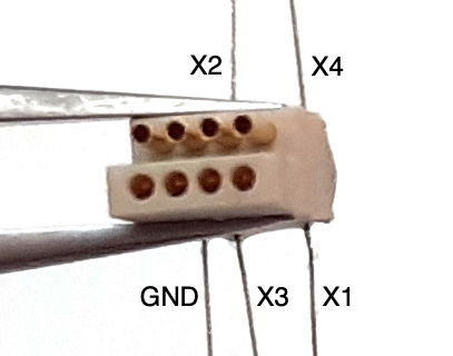
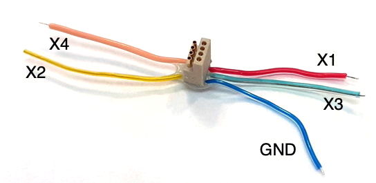
[10-OCT-25] Each EIF is built around a connector. The EIF8 is built around the A79614, also called the PZN-08-AA. This connector is both polarizing and hermaphroditic, in that the connector mates with another like itself. The table below shows which pins are used and lists their functions. When we connect a wire to one of these pins, it will either be insulated with clear teflon, or it will be insulated with brightly-colored silicone. We always use the same bright color with each pin, although we did stop using salmon leads for P-8 and started using purple instead.
| Pin Number | Slicone Color | Functions | Comments |
|---|---|---|---|
| P-1 | blue | GND | HMT circuit ground. Acts as iEEG reference potential. |
| P-2 | none | none | unused |
| P-3 | green | X3/X3+ | iEEG or EMG+ |
| P-4 | yellow | X2 | iEEG |
| P-5 | none | none | unused |
| P-6 | none | none | unused |
| P-7 | red | X1 | iEEG |
| P-8 | purple (was salmon) | X4/X3− | iEEG or EMG− |
The contacts are on a 0.025" (0.635 mm) spacing. To construct an EIF8, we clip the connector leads back, bend them towards the center-line of the connector and solder our leads onto the reduced pins. We wash and dry, then apply epoxy to encapsulate the joints. When we inspect the wires after the epoxy has cured, we reject any EIF with more than half a millimeter of exposed wire outside the epoxy.
Only one pin on the connecter has a constant and ever-present function: the ground lead. This is P-1, always blue. Even if we use the EIF to measure EMG in two locations on the neck with a differential amplifier, we must still ground the HMT with respect to the animal's body using the blue ground lead. The other four leads of an EIF8 have functions that vary with the version of HMT we mount upon the EIF8. A four-channel HMT with four iEEG inputs will use the GND lead as its reference potential, and the leads will be X1, X2, X3, X4, and GND. A two-channel iEEG, single-channel EMG HMT will use P-7 and P-4 as X1 and X2 for iEEG, referred to P-1 as GND, and it will use P3 and P-8 as X3+ and X3− for EMG.
[10-OCT-25] The EIF must be cemented to the skull of the subject animal. For a detailed description of the procedure, see our HMT Surgery Protocol, iEEG and HMT Surgery Protocol, iEEG and EMG. We provide summary information below.
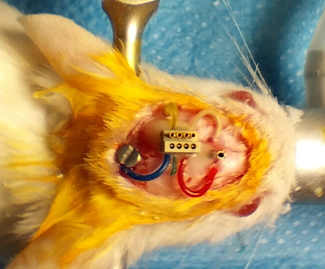
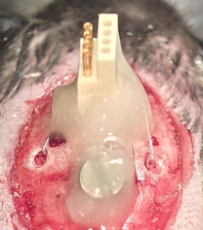
Loading the EIF8 on a mouse skull is a delicate operation. There is a shortage of space. We want the EIF to sit as close to the skull as possible, so that the HMT to which it attaches will protrude as little as possible from the mouse's head. When implanting an EIF8 equipped with two depth electrodes, two skull electrodes and a ground electrode, space is limited for clamp fixtures, making it harder to place all components directly on the skull. Once all the leads, electrodes, and connectors are in place, we cover with dental cement to create a headplate.
When it comes to recordings down to 0.0 Hz (DC recordings), we recommend against using a screw with silver leads, so silver leads should be cemented in place. In the Kate Hills protocol, there are no screws fastening the leads into their holes, only cement. As a result, there is more space for the surgeon to work in. So far as we can tell, the cemented leads are just as stable and quiet as leads held in place by screws.
[10-OCT-25] Today we retire the original EIF part numbering scheme. Here are the original part numbers for your reference. We are happy to help you determine the new part number that corresponds to older part numbers you may have ordered in the past.
| Version | Leads | Price (US$) |
|---|---|---|
| EIF8-AAAA | All: 316SS, coil of 50-μm wire, 250 μm dia, colored silicone 500 μm, 1 mm bare coil | 100 |
| EIF8-XAAX | All: 316SS, coil of 50-μm wire, 250 μm dia, colored silicone 500 μm X1,X4: X-Electrode, Others: 1 mm bare coil |
200 |
| EIF8-XAAA | All: 316SS, coil of 50-μm wire, 250 μm dia, colored silicone 500 μm X1: X-Electrode, Others: 1 mm bare coil |
150 |
| EIF8-YAAA | All: 316SS, coil of 50-μm wire, 250 μm dia, colored silicone 500 μm X1: Y-Electrode Others: 1 mm bare coil |
200 |
| EIF8-BBBB | All: 316SS, annealed, 50 μm dia, teflon 115 μm dia, square-cut tip | Discontinued |
| EIF8-EE | X1, X2, GND: 316SS, annealed, 75 μm dia, teflon 140 μm dia, square-cut tip X3, X4: omitted. |
150 |
| EIF8-EEEE | All: 316SS, annealed, 75 μm dia, teflon 140 μm dia, square-cut tip | 150 |
| EIF8-SSSS | All: 316SS, stranded, 76 μm dia, teflon 140 μm dia, square-cut tip | 100 |
| EIF8-CCCC | All: 316SS, annealed, 125 μm dia, colored silicone 350 μm dia, square-cut tip | 100 |
| EIF8-DDDD | All: 316SS, annealed, 125 μm dia, teflon 200 μm dia, square-cut tip | 100 |
| EIF8-MMMM | All: Strain-relieved silver, 125 μm dia, colored silicone, square-cut tip | Discontinued |
[30-JUL-25] For design files and development logbook, see the EIF design and development page at DEIF.