[06-MAR-26] We supply a variety of lead terminations and electrodes for use with our Subcutaneous Transmitters (SCTs), Head-Mounting Transmitters (HMTs), and Implantable-Stimulator Transponders (ISTs). An electrode is a component designed to acquire the electrical potential at a particular location in an animal's body. A termination is an electrically conducting component at the end of a flexible lead that is designed to connect to an electrode or to itself act as an electrode. For electrode implantation instructions, see our Electrode Surgical Protocls page.
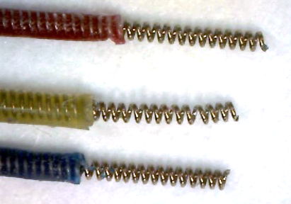
The "B-Screw" termination is a steel screw soldered to the end of a flexible lead in such a way that the slot in the head of the screw is free for us to turn the screw into a skull hole. The screw itself will act as the electrode. The "D-Pin" termination is a gold-plated pin soldered to the end of a lead that mates with an "E-Socket" mounted of a depth electrode. But the "A-Coil" termination, on the other hand, is 1 mm of bare steel coil at the end of a lead that itself will be used as an electrode. We deploy it as an EEG electrode by straightening it, bending it, cutting it short, and fastening it in place with a screw. A "P-Coil" termination is 3 mm of bare steel coil. The "S-Coil" is 2 mm of bare steel coil with 2 mm of silicone insulation at the lead tip. The S-Coil is our Soft Tissue Electrode.
For a separate discussion of silicone-insulated electrode leads, see Flexible Wires. For instructions on soldering stainless steel wire and screws, see Solder Joints. For a discussion of the sources of the electroencephalogram (EEG), see The Source of EEG. For calculation and estimates of electrode impedance, see Electrode Impedance. For a presentation of the behavior of various electrode metals in response to DC signals, see Step Response of Metal Electrodes.
[08-NOV-25] Each lead of the a Subcutaneous Transmitter (SCT) or Implantable Stimulator (IST) has its own termination, and each type of termination has a name. In the following table, we provide drawings and part numbers for the components we solder to the end of a lead. The hyperlink we provide for the K-Screw, for example, is a link to a drawing of the K-Screw. The completed K-Screw electrode, however, is a lead soldered to a K-Screw.
| Name | Description |
|---|---|
| A-Coil | C-Lead or A-Lead coil 316SS, length 1 mm. |
| B-Screw | Screw, 0-80 thread, dia 1.6 mm, length 3.2 mm, slotted. |
| C-Screw | Screw, M0.5 thread, dia 0.5 mm, length 0.6 mm, flat. |
| D-Pin | Pin, dia 0.30 mm, length 2.1 mm, Mill-Max 4353-0-00-15-00-00-33-0, mates with E-Socket. |
| E-Socket | Socket, for pin dia 0.20-0.33 mm, Mill-Max 4428-0-43-15-04-14-10-0 |
| F-Pin | Pin, dia 0.64 mm, length 4.1 mm, Mill-Max 5035-0-00-15-00-00-33-0, mates with E363/0. |
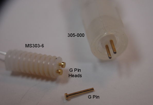
| G-Pin | Pin, dia 0.51 mm, length 4.4 mm, Mill-Max 5063-0-00-15-00-00-33-0, mates with MS303/6. |
| I-Pin | Pin, dia 0.30 mm, length 3.9 mm, Mill-Max 9083-0-00-15-00-00-38-0, mates with E-Socket. |
| K-Screw | Screw, 00-90 thread, dia 1.2 mm, length 1.6 mm, slotted. |
| L-Screw | Screw, 000-120 thread, dia 0.86 mm, length 1.6 mm, T1 Torx. |
| M-Wire | Solid wire, 125 μm dia Ag, insulation 250 μm silicone, length 15 mm. |
| N-Pin | Pin, dia 0.38 mm, length 3.2 mm, Mill-Max 4689-0-00-15-00-00-33-0. |
| P-Coil | C-Lead or B-Lead coil 316SS, length 3.0 mm. |
| Q-Ferrule | Crimp ferrule, length 2.0 mm, with 316SS coil, with inner dia 250 μm. |
| S-Coil-C | C-Lead coil 316SS length 0.8 mm, 1.6 mm insulation at tip, for soft tissue electrode. |
| S-Coil-B | B-Lead coil 316SS length 2.0 mm, 2.0 mm insulation at tip, for soft tissue electrode. |
A lead termination may itself be used as an electrode, or it might connect to a depth electrode during surgery. The A-Coil termination is almost always deployed as an electrode. But D-Pin always mates with an E-Socket on a depth electrode. The table below presents our depth electrodes.
| Name | Part Number | Description |
|---|---|---|
| H-Electrode | SDE-H | Depth electrode, wire 125-μm dia Pt-Ir, insulation 200-μm dia teflon. Locate with guide cannula, E-Socket mates with D-Pin termination. Obsolete. Guide cannula removed during surgery. Discontinued. |
| J-Electrode | SDE-J | Depth electrode, 125-μm dia 316SS wire, insulation 200-μm dia teflon. Locate with guide cannula, E-Socket mates with D-Pin termination. Guide cannula removed during surgery. |
| R-Electrode | SDE-R | Depth electrode, straight wire 125-μm dia 316SS, insulation 200-μm dia teflon. Locate with guide cannula, E-Socket mates with D-Pin termination. Guide cannula remains in place after surgery. |
| W-Electrode | SDE-W | Depth electrode, straight wire 125-μm dia 316SS, insulation 200-μm dia teflon. Locate with hypodermic tube, E-Socket mates with D-Pin termination. |
| X-Electrode | SDE-X | Depth electrode, wire 125-μm dia 316SS, insulation 200-μm dia teflon. Locate with hypodermic tube, crimp wire into Q-Ferrule. |
| Y-Electrode | SDE-Y | Depth electrode, wire 75-μm dia 316SS, insulation 140-μm dia teflon. Locate with hypodermic tube, crimp wire into Q-Ferrule. |
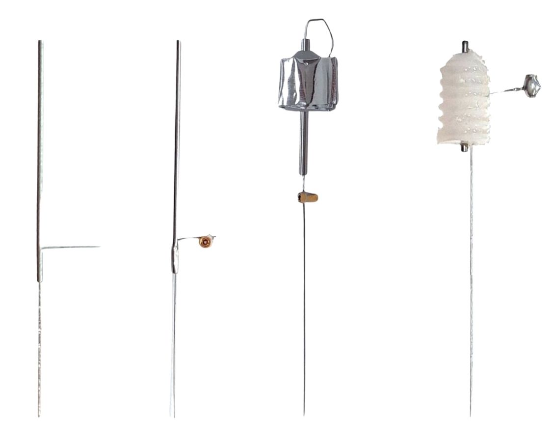
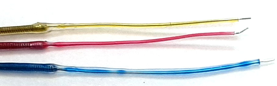
By default, we solder screws, pins, and sockets perpendicular to leads and wires. But if we precede the electrode letter code with a lower-case "s", the pin, screw, or socket is parallel to the lead or wire, as shown below.
Some lead terminations can act as electrodes themselves. The screws we can push into a skull hole. The bare coil we can straighten and bend to fit in a skull hole.
Whatever we attach to the ends of the SCT leads must be small enough to be drawn up under the skin of the neck to the head. If we want to use a depth electrode with an SCT, we connect the depth electrode to the lead during surgery using a pin and socket contact or a crimp contact. Order depth electrodes at the same time as your transmitters, and we will try to make sure your transmitter leads have matching terminations. The pin and socket connection is slightly easier to perform than the crimp contact, but the crimp contact generates less noise.
See SCT Implantation for an introduction to the implantation procedure. See the Insulation Removal chapter of our Flexible Wires page for instructions on removing silicone from the ends of our spring leads. See the Solder Joints chapter of the same page for instructions on tinning bare stainless steel wire in preparation for soldering to your own screws and pins.
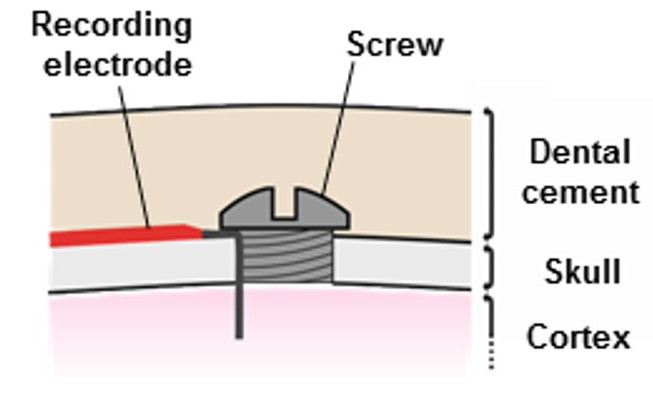
[04-MAR-26] A fastening screw is a screw used to hold an electrode, lead, or cement fixture to a bone. A fastening screw is not itself an electrode, although it may be in contact with an electrode. We will provide fastening screws for use with your SCTs and HMTs if you request them. The most common use of fastening screws during implantation of SCTs and HMTs is to hold a bare wire electrode in place in a skull hole. We describe how we secure a bare wire in place with a fastening screw in the Coiled Wires chapter of this page.
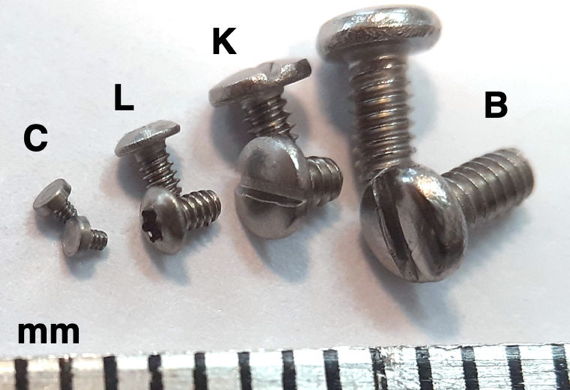
We stock four sizes of screw for implantation. We assign each a letter code for use when ordering transmitters. The table below gives the dimensions of each type, and provides a link to a drawing. These screws can also be soldered to electrode leads, in which case we call them screw electrodes instead of fastening screws.
| Order Number | Name and Drawing | Type | Diameter (mm) | Pitch (mm) | Length (mm) | Head (mm) |
|---|---|---|---|---|---|---|
| SCREW-B | B-Screw | 0-80 1/8" | 1.52 | 0.32 | 3.2 | Slotted |
| SCREW-K | K-Screw | 00-90 1/16" | 1.2 | 0.28 | 1.6 | Slotted |
| SCREW-L | L-Screw | 000-120 1/16" | 0.86 | 0.21 | 1.6 | Torx T1 |
| SCREW-C | C-Screw | M0.5-0.125-0.6 | 0.50 | 0.125 | 0.6 | Flat |
The smallest screw, which we call the C-Screw, has no slot in its head. When we use it to hold a wire in place, we are using it more as a plug than a screw. Its threads hold it in place in the skull hole and we later cover with dental cement. The smallest screw that provides a head is our L-Screw, which provides a Torx T1 head, for which you will need to obtain from us a Torx T1 driver. The K-Screw and B-Screw both provide slots for a flat-head screwdriver. The C-Screw and L-Screw are used as fasteners only in mice. The K-Screw is used in mice and rats. The B-Screw is used only in rats.
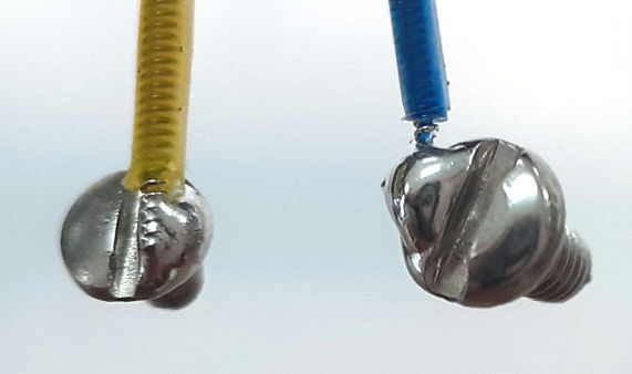
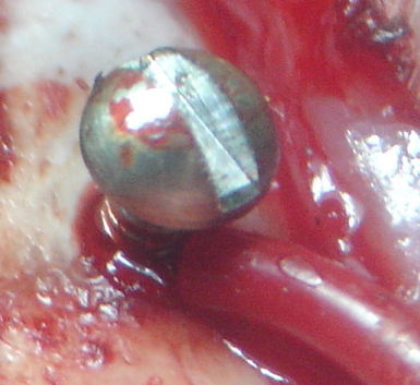
[29-JUL-25] We make a screw electrode by soldering the end of a lead to a screw. Now the screw itself becomes the electrode that picks up the biopotential we wish to record. If the screw is large enough, we can solder the tip of the lead to one side of the slot in the screw head, allowing the surgeon to turn the screw with a screwdriver. If the screw is too small, we simply solder the lead to the entire screw head, covering the slot or socket. Instead of turning these screw electrodes in place, we simply push them into the skull hole. Our B-Screw and K-Screw electrodes are made by soldering a lead to one side of the slot in a B-Screw and K-Screw respectively. Our C-Screw and L-Screw electrodes are made by soldering a lead to the entire head of a C-Screw and L-Screw respectively.
When we plan to turn our screw electrode into its skull hole, as we might for a B-Screw or K-Screw, we must account for the fact that the lead soldered to the screw will rotate as we rotate the screw. If we simply place the screw on our skull hole and rotate, the lead will be twisted when the screw is in position, which causes it to push outwards from the skull in a manner that hinders our covering the screw with cement. So we hold the screw electrode with tweezers and insert our screwdriver. We rotate counter-clockwise three turns, then insert the screw into the skull hole and rotate clockwise three turns. Now the screw is in place and the lead is not twisted.
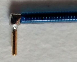
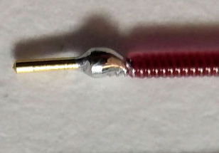
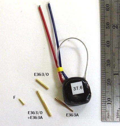
[29-JUL-25] Gold-plated pins allow us to connect the end of our EEG lead to depth electrodes. If we are implanting a transmitter with two incisions, we must tunnel the lead ends under the skin to the skull. A depth electrode is too cumbersome to tunnel beneath the skin, but a pin is easy to grab hold of with tweezers and drag along the tunnel. Our contact pin terminations are designed to work with depth electrodes. All these pins are made by Mill-Max. The photograph below shows our D Electrode, which mates with our W, J,and R Electrodes.
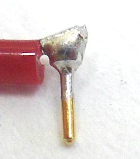
These pins provide a gold-plated finish, which mates well with the gold-plated finish of a socket, to provide a corrosion-resistant electrical contact within dental cement saturated with water vapor.
Our F and G-Pin terminations mate with cerrtain electrodes made by Protech International (formerly known as Plastics One). When you choose an electrode with a socket, we will look at the socket drawing and choose a pin that will fit sungly and take up as little vertical height as possible, to keep your implantation compact.
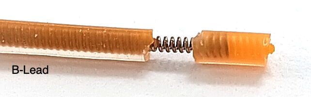
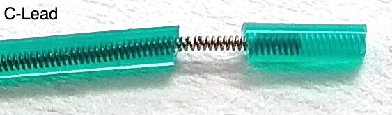
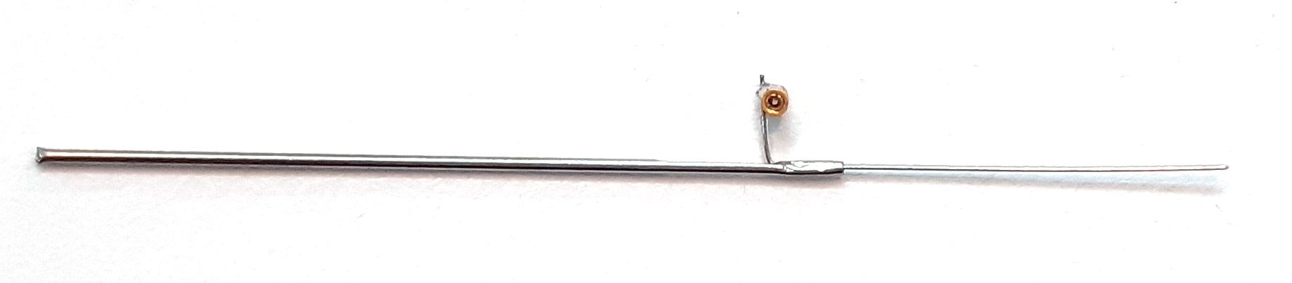
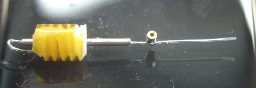
[11-NOV-25] A crimp contact is one where we join two wires by compressing a ferrule and relying upon elestic compression between the two wires to hold them in contact. We call the steel tube the crimp ferrule. With a 316SS stainless steel ferrule and two 316SS wires to join, no solder is involved. We eliminate the chemical artifact that is generated by the galvanic potential between solder and steel, and by the reaction between saline and a solder joint. In our case, we combine the ferrule and a P-Coil at the end of one of our B-Leads to make what we call a "Q-Ferrule". The Q-Ferrule accepts the end of a solid steel wire into the center of its P-Coil, and we squeeze the ferrule to make the connection. The P-Coil within the Q-Ferrule acts as a compression sring, pushing outwards on the ferrule and inwards on the solid wire at its center.
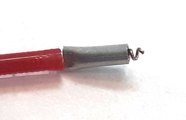
Our crimp ferrules are laser-cut, thin-walled, 2-mm lengths of stainless steel tube. You can buy these from us under part number CF-1. To construct a Q-Ferrule, we slide the CF-1 onto a P-Coil. We squeeze the ferrule at the base of the P-Coil so as to hold it in place. We trim the end of the P-Coil so that only half a millimeter of spring coil protrudes from the ferrule. The Q-Ferrule acts as the receptacle side of the cripm contact. The plug side will be 2 mm of bare 125-μm diameter stainless steel wire. This we slide into the center of the Q-Ferrule coil. We push the wire in as far as it will go. We squeeze the ferrule with pliers to complete the contact.
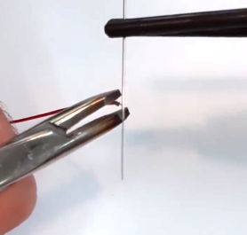
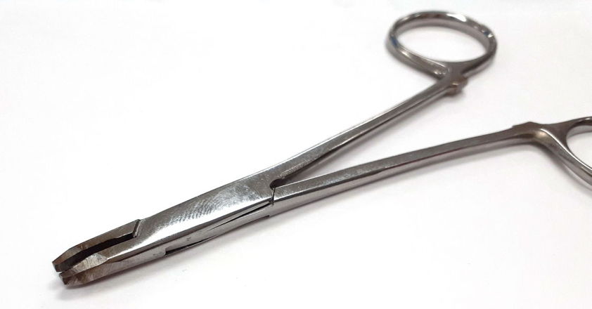
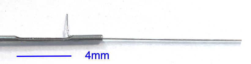
The crimp contact requires that the bare steel wire enter the central cavity of the spring coil in the Q-Ferrule. The spring in our B-Leads has outer diameter 450 μm and inner diameter 250 μ. A bare 125-μm diameter steel wire fits easily into the coil of the spring. The ferrule is 2-mm long with inner diameter 510 μm and 50-μm walls. The ferrule squashes the spring coil and wire together, creating a press-contact that is maintained despite movement and stress by the compression of the spring. To perform the crimp, we recommend modified forceps, like the ones shown below. We cut off the forcep clamps, we cut short the forcep jaws, and we grind the jaws down until they are 2 mm wide at the tip and 4 mm high. During surgery, we hold the Q-Ferrule in the jaws of these pliers, and slide it over the bare steel wire to which we want to make a crimp contact. We squeeze as tightly to squash the ferrule.
When you want to make a crimp contact, specify the Q-Ferrule with the letter "Q" in your part sensor part number's electrode list. When re-using an SCT, you may want to re-create a Q-Ferrule on the end of the lead. You must obtain the ferrules from us, but assuming you have them, construction of your own Q-Ferrule is straightforward. The most difficult part is removing insulation from the end of the lead. Follow the instructions in the Insulation Removal chapter of our Flexible Wires manual and remove 3 mm of insulation from your lead.
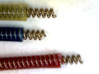
[01-JUN-26] Of all our electrodes, the "bare wire electrode" is the most popular. We make a bare wire electrode by stretching, bending, and trimming an A-Coil termination. All our spring leads contain a 316 stainless steel coil conductor. By removing one millimeter of insulation from the end of a spring lead, we create an A-Coil. For more information about the springs wires, see the Spring Leads chapter of our Flexible Wires page. To remove insulation from the end of a spring lead yourself, consult the Insulation Removal chapter of the same manual.
By far the most common use of the A-Coil is to create an angled wire for insertion into a skull hole. We stretch out the coil and bend the straightened wire at right angles.
The A-Coil can be re-created at the end of a freshly-cut lead with the help of a scalpel. When we re-use an implant, the simplest procedure is to cut off the ends of the leads to free them from the cement used to hold them in place in the first implantation. We create a new A-Coil by removing insulation from the cut lead. When you order an SCT, you specify the insulated length of the leads. Add 5 mm for each time you want to be able to cut the leads back and re-implant your telemetry device. We use a scalpel to remove silicone from the tip of the lead so as to expose the bare wire. Consult the Insulation Removal chapter of our Flexible Wires page for instrutions on removing insulation from our 0.5-mm and 0.7-mm spring leads.
Electrodes that are free of solder, such as the bare wire secured with a steel screw, generate less low-frequency chemical artifact than electrodes that contain an exposed solder joint.
For instructions on how to use the A-Coil to record intracranial electroencephalogram (iEEG), see the Implantation chapter of the Telemetry Manual.
[10-APR-24] We make straight, silicone-insulated, solid-wire electrodes by soldering a solid wire into the spring before we coat with silicone. In order to hold a reliable coat of silicone, the wire must be at least 125 μm in diameter. Our M-Wire is 125 μm bare silver wire we have soldered into a spring and insulated.
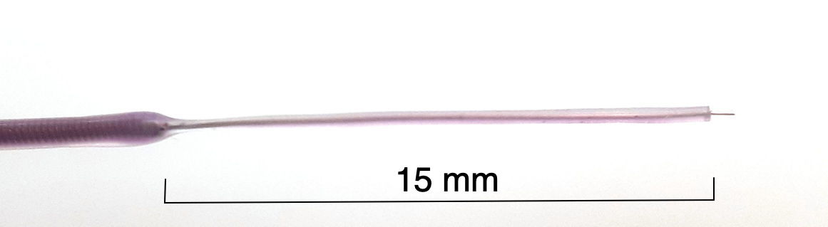
We can use the tip of the M-Wire as an electrode of diameter 125 μm, or we can remove some of the silicone insulation to make a longer electrode. We remove silicone from the end by cutting around the wire with a sharp scalpel and a gentle hand, then removing the detatched silicone segment.
There is little point in attaching a solid stainless steel wire to the end of one of our electrode leads. The steel wire inside the lead is perfectly adequate whenever we want a stainless steel contact. Platinum or platinum-iridium might be useful as a solid wire, but we have not yet been asked to make them.
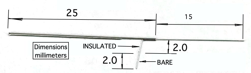
[09-MAR-26] When we want to detect biopotentials in soft tissue, such as a muscle, the stomach, or any other organ or interior cavity, we use a "soft tissue electrode", or "S-Coil". To make an S-Coil at the end of a B-Lead, we begin with an "A-Coil", which provides 1 mm of bare steel coil protruding from the end of the lead insulation. We cut through the silicone insulation 2 mm from the end of the insulation. We take care not to cut through the wire inside the insulation. When we have completed the cut around the wire, we take the insulation at the end of the wire in our right hand. We do not squeeze tightly, but instead hold it just firmly enough to stop it slipping out of our fingers. We take the rest of the lead in our left hand, holding it firmly a few millimeters away from our cut. We rotate the lead with our left hand while holding the tip stationary in our right hand. We turn the lead in such a way that the insulation at the tip starts to separate from the rest of the lead. Steel coil emerges from the insulation. The 1-mm tip of the A-Coil disappears into the 2-mm section of insulation at the tip. We keep unscrewing the coil until the end of the coil is half-way through the insulation at the tip. We now have 2 mm of bare coil exposed near the end of the lead. And we have 2 mm of silicone insulation attached to the end. Within the 2 mm of insulation we have the original 1 mm of bare steel of our A-Coil, and we have 1 mm of silicone with a narrow, empty helical channel inside. This 1 mm of silicone at the tip is the insulator we need to make sure that our soft tissue electrode does not record the biopotential outside our target tissue. To make an S-Coil out of a C-Lead we do not start with an A-Coil. Instead, we cut the end of the lead flush with a sharp pair of iris scissors. We cut around the insulation 1.6 mm from the tip rather than 2 mm from the tip. We must take even more care with the C-Lead than with the A-Lead to avoid cutting through the wire inside. The C-Lead wire is only 50 μm in diameter, compared to 100 μm for the B-Lead wire. We unscrew the tip in the same way we do for the B-Lead, but we stop when we have moved the 1.6-mm section of insulation a mere 0.8 mm along the lead. We now have 0.8 mm of exposed bare coil and 1.6 mm of insulation at the tip.
To embed the S-Coil in soft tissue, we pass a needle through the surface of the tissue. We thread the S-Coil into the needle. When we re move the needle, it leaves the S-Electrode behind. We arrange for the bare steel coil to be hidden within the tunnel we have made in the surface of the soft tissue. The silicone tip can either stick out or remain embedded in the tissue. If it sticks out, we can suture it to the soft tissue to fasten the electrode in place. In any event, we should suture the lead on the far side of the exposed steel so that the electrode is held in place where the lead enters the tissue.
Our customers have used soft tissue electrodes to record ECG by placing two such electrodes on either side of the thoracic cavity. There is no need to suture to the heart to obtain a strong ECG signal. They have recorded EGG from the stomach by suturing their soft tissue electrodes directly to the outer wall of the stomach. Our customers have recorded EMG by securing soft tissue electrodes in the muscles of the necks of mice and rats. For a detailed surgical protocol for our soft tissue electrodes, see Electrode Surgical Protocols.
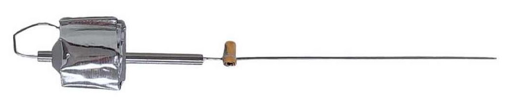
[18-MAR-26] To reach farther into brain, we need a stiff, insulated wire. The wire will come supplied longer than you need. You cut the wire back to the length you require. You can square-cut the end, or you can cut it at an angle so that it has a bevel to better penetrate the brain. When implanting with a subcutaneous transmitter (SCT), we run the SCT lead along the surface of the skull to the electrode and attach the lead to the electrode either with a crimp contact or a socket contact. During surgery, the depth electrode must be held firmly while we make this contact. Afterwards the electrode must be maneuvered into the correct location on the skull and lowered to the correct depth.
Each electrode provides a mounting fixture by which we can hold the electrode during surgery. In the case of the X and W-Electrodes, the mounting fixture is a laser-cut steel tube, which we call our Depth Tube. In the case of the R and J-Electrodes, the mounting fixture is a threaded plastic pedestal. Within the pedestal is a steel cannula guide. To secure an electrode to the skull, we place an anchor screw through the skull nearby and enclose the depth electrode and the anchor screw with cement. Depending upon the type of electrode, we either remove the mounting fixture and seal with another layer of cement, or we leave the mounting fixture intact to act as a cannula guide.
The standard X-Electrode, part number SDE-X, has wire length 15±1 mm, allowing the user to cut it back to the length they want. If you know your desired length ahead of time, we can cut the wire to a length as short as 1.5 mm with accuracy ±0.2 mm. The electrode with wire length "x.y" millimeters has part number SDE-X-XMY. Part number SDE-X-1M6, for example, is an X-Electrode with wire length 1.6±0.2 mm.
The X-Electrode provides a 450-μm diameter stainless steel tube as a mounting fixture. To hold the tube, we recommand a clamp like the RWD 68201, which attaches to your stereotactic mount. The tube has a slot cut into it, out of which we run the electrode wire for connection to an electrode lead with a crimp contact. Because the crimp contact does not contain any solder, the signal recorded by the electrode will contain far less low-frequency chemical artifacts. Crimp contacts allow us to record slow signals like cortical spreading depolarization (CSDs). For the crimp contact, we must use one of our B-Leads with a Q-Ferrule on the end, which provides the ferrule and spring side of the crimp contact.
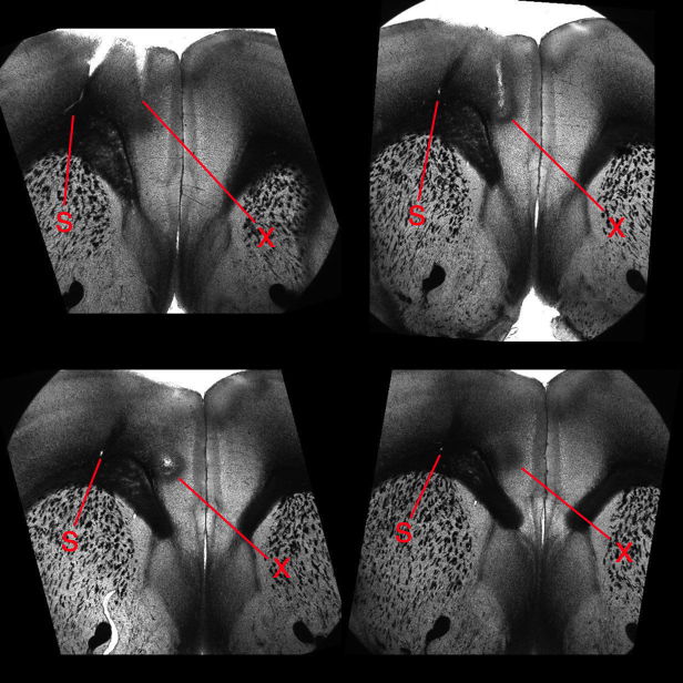
Any wire we bury in body tissue will cause damage and scarring. For an example of damage caused by an implanted X-Electrode and neighboring injections, see these brain slices, which show damage to the brain of a mouse caused by injection and recording.
The Y-Electrode, part number SDE-Y, is similar to the X-Electrode, but is equipped with a thinner wire, which in theory will cause less trauma to brain tissue. The Y-Electrode wire is 140-μm teflon insulation around a 75-μm solid 316SS wire. For details see photograph and drawing. The standard Y-Electrode, part number SDE-Y, has wire length 5±0.5 mm, allowing the user to cut it back to the length they want, but we can cut the wire to lengths as short as 1.5 mm with accuracy ±0.2 mm. Part number SDE-Y-XMY has wire length "x.y" millimeters.
The R, W, J, and H-Electrodes all provide a socket into which we can plug a gold-plated pin. The pin that fits the socket is the D-Pin termination that we can provide at the end of any subcutaneous lead. The W-Electrode, part number SDE-W, is an X-Electrode equipped with a socket. The W-Electrode introduces two solder joints into the electrode: one between a spring coil and the pin, and the other between the electrode wire and the socket. Do not use W-Electrodes to record cortical spreading depressions. The W-Electrode is easier to implant than the X-Electrode because sliding a pin into a socket is easier than crimping a ferrule onto a bare wire.
Our drawing of the W-Electrode is identical to that of our X-Electrode, except that the bare wire of the X-Electrode has a socket soldered to it. The standard SDE-W part has wire length 15±1 mm, but the SDE-W-XMY part has wire length "x.y" millimeters as short as 1.5 mm and with accuracy ±0.2 mm.
The R-Electrode, part number SDE-R, provides a cannula through which we can inject a substance into subject animal's brain, and an adjacent electrode wire through which we can record local field potental. The standard SDE-R part has wire length 10±1 mm. The SDE-R-XMY has wire length "x.y" millimeters within the range 1.5 mm to 15 mm. We cut the shortest wires with accuracy ±0.2 mm. The R-Electrode guide cannula provides a threaded pedestal onto which we screw a dummy cannula to seal the guide tube when it is not in use. We ship every R-Electrode with a dummy cannula. To deploy an R-Electrode, we use a stereotactic clamp that grabs the pedestal.
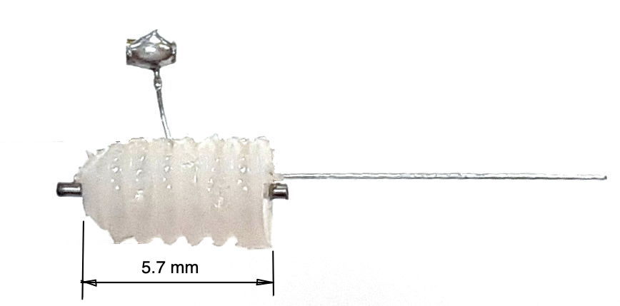
The R-Electrode wire is parallel to the cannula tube and emerges 150±150 μm from the guide tube at the base of the pedestal. The pedestal itself is 5.7 mm long. The cannula guide is the a modified C315GS-5/SP from Protech International. We grind down the C315GS-5/SP's guide tube until it protrudes only 0.5 mm beneath the pedestal, which is the length we need to make an R-Electrode. The cannula tube is stainless steel, 26-gauge, inner diameter 250 μm, outer diameter 470 μm. The dummy cannula we ship with the R-Electrode is the C315DCS-5/SPC.
The J-Electrode, part number SDE-J, provides a straight stainless-steel wire mounted to a within a steel cannula guide. We connect our electrode lead to the J-Electrode by means of a socket soldered to the wire. The wire is insulated below the socket, but it is bare above the socket. The cannula guide is a C313GS-5/SP from Protech International. The guide pedestal is a threaded plastic pice 5.7 mm long. The guide cannula is a steel tube cut 5.0 mm below the pedestal. The tube is stainless steel, 22-gauge, inner diameter 390 μm, outer diameter 710 μm.
To deploy a J-Electrode, we need a stereotactic clamp that grabs the pedestal. Once the J-Electrode is in position, we cover the socket with cement, but we take care not to bury the tip of the cannula tube. We cut the bare steel wire where it emerges from the top of the cannula pedestal and raise the cannula off the wire. We cut the wire off where it emerges from the existing cement, and cover the exposed wire tip with more cement. The advantage of the J-Electrode over the X and W-Electrodes is the ease with which we can cut the J-Electrode wire and remove the guide.
The standard J-Electrode, part number SDE-J, has wire length 10±1 mm, where the wire length includes the diameter of the socket. The SDE-J-XMY has wire length "x.y" millimeters, within the range 3 mm to 15 mm. We cut the shortest wires with accuracy ±0.3 mm. In J-Electrode Implantation you will find a pictoral surgery protocol provided by ION/UCL. In the J-Electrode chapter of our Electrode Surgical Protocols page, you will find our own, very similar, recommended J-Electrode implantation protocol.
The H-Electrode is obsolete. It provided a platinum-iridium wire, but was otherwise similar to the J-Electrode. Now that we have a reliable source of straightened, full-hardened stainless steel wire, we no longer make electrodes with platinum-iridium wire. The stainless steel is much stiffer, and when it comes to depth electrodes, stiffer is better. If, however, a customer should request a depth electrode made out of platinum-iridium, we still have the wire on the shelf, so we will be happy to update the old H-Electrode design to match the latest J-Electrodes, or any other of our depth electrodes.
[08-NOV-25] We recommend against using conductive epoxy as a means to fasten an electrode to the skull to record electroencephalogram (EEG). We experimented with conductive epoxy in the early days of our telemetry system. We recorded useful ictal activity with wires cemented into skull holes with conductive epoxy, but the baseline of these signals was constantly drifting, and movement artifacts were frequent and severe. It is an attractive prospect to clear a space on the skull and glue a wire to the bone with conductive epoxy, but even if we ignore the baseline swings and the movement artifacts, the amplitude of the signal we obtain from these electrodes is less than half that we obtain with a wire held in a burr hole with a screw. The wire in the burr hole, which we call a "bare wire surface electrode" records a stronger signal, a more stable signal, and if properly insulated with dental cement, will produce no movement artifacts. If your experiment requires that you avoid drilling a hole through the skull, we suggest that you contact us to discuss a steel square electrode that we believe will be far superior to conductive epoxy. We will solder a 3-mm square of 316SS to the end of your electrode leads. You cement these directly to the skull surface with cyanoacrylate, and insulate over the top with dental cement. Such an electrode causes minimal trauma to the skull, will record the same amplitude as a conductive epoxy electrode, but its attachement will be more reliable, and artifacts less severe.
[30-MAY-17] The movement of electrodes with respect to the surrounding animal tissue will add step-changes in potential to the intracranial electroencephalogram (iEEG) signal. By default, we equip the amplifiers in our SCTs with a high-pass filter with cut-off frequency 0.3 Hz. When a step-change passes through this high-pass filter, it come out looking like a pulse with a sharp front edge, followed by a relaxation half a second long. The theoretical step response of the A3028B, for example, is the blue graph shown here. If we solder the two leads of a transmitter together, drop the transmitter in water, and stir it around, the standard deviation of the signal is less than 20 μV and we see no step artifact. If we separate the leads and allow them to measure the variation in electric potential in the water as we stir, we see 1-mV rumble, but not sharp steps. When we allow the electrodes to make intermittent contact with one another as we stir that we start to see 10-mV steps in the signal. We call these steps "movement artifact". The longer-term changes in potential that we observe with amplifiers that have no high-pass filter we call "chemical artifact", and we discuss those artifacts separately.
Movement artifact arises in iEEG recordings when the electrodes are not secured with respect to the skull. As implanters have learned to secure wires and screws more effectively to the animal skull, the frequency of these artifacts has decreased. In mice, these artifacts are particularly difficult to eliminate. Here are some examples of movement artifact from mouse recordings.
Here we see pulses caused by steps of order 10 mV, which are shaped into pulses by the transmitter's high-pass filter. In the figure below we see far larger artifact from the same M0.5 skull screws in another mouse.
Here we see large artifact with more complex progression, also from skull screws in a mouse. The amplitude is 15 mVpp.
We are not certain of the origin of the following features. The two traces are from a dual-channel transmitter implanted in a mouse. If the electrode potential of the common electrode changes, we expect the effect upon the X and Y channels to be shared. If the electrode potential of either X or Y changes, we expect to see the effect only on X or Y. Here we see opposite changes in X and Y.
The number of movement artifacts in a recording varies greatly from one implant to the next, and is a strong function of who performs the surgery. Recordings from rats tend to have fewer than one artifact per hour for all experienced implanters. Movement artifact in mice varies from fewer than one per hour to hundreds of artifacts per hour. Those implanters whose recordings are almost free of artifact have reduced the artifact rate by working on better anchoring of their electrodes on the mouse skull. We are currently working on developing a guide to successful implantation in mice.
[24-JUN-25] Our standard SCTs and HMTs are AC transmitters. They provide a 0.2-Hz high-pass filter to remove steady-state galvanic potentials generated by the electrodes, and also to attenuate slow changes in these galvanic potentials. If we want to look for phenomena such as cortical spreading depolarizations (CSDs), or slow changes in electrogastrogram (EGG), we must use a DC transmitter. The passband of our DC transmitters extends all the way down to zero Hertz (0.0 Hz). Any SCT or HMT with a "Z" in its part number is a DC transmitter. To convert an AC transmitter into a DC transmitter, we remove the high-pass filter and reduce the gain of the amplifier. Once we extend the passband down to 0.0 Hz, we must concern ourselves with changes in galvanic electrode potential. These changes take place over tens of seconds, or they can be semi-permanent and of order tens of millivolts. We decrease the gain of DC transmitters so as to increase their input dynamic range, which ensures that we can accommodate these changing galvanic potentials. When a galvanic potential varies over a period of tens of seconds, we call the variation a chemical artifacts. Solder joints combined with stainless steel will generate a sustained galvanic potential when immersed in saline, and variations in this galvanic potential appear in our recordings as chemical artifact. No matter how hard we try to keep water off a solder joint in a head fixture, it makes its way to the solder joints and generates chemical artifact. Here is an example of chemical artifact recorded from a mouse with depth electrodes that use soldered pins and sockets.
To reduce chemical artifact, we eliminate solder joints. One way to eliminate solder is to use a crimp contact between our lead and depth electrode. Another way is to hold a bare steel wire in place on the skull with a screw. The crimp contact provides better immunity to movement.
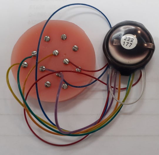
[18-JAN-19] We would like to compare the number of chemical artifacts generated by crimp and screw contacts. Both these contacts are free of solder, but the crimp contact is secured by a squashed steel ferrule pressing on a spring, while the screw contact is secured by a thread pressing a wire into a rigid mounting material such as bone or, in our experiment, dental cement. We take two transmitters with bandwidth 0-160 Hz and place them in 1% saline in two separate petri dishes, as shown below.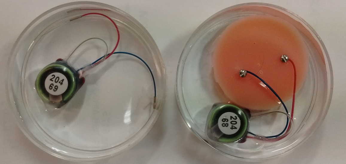
One device we equip with two crimps, one leading nowhere and one connecting to a bare steel wire. The other device we equip with two screws and a mock animal skull made out of dental cement. We record continuously for two days within a faraday enclosure that is disturbed only be changes in ventilation and lighting.
During the night, when the lights are off in the OSI office, nobody is moving around, and nobody is touching the table upon which our experiment is running, the recordings are like the example shown below.
During the day, we see step changes in potential followed by relaxation on both channels. We call these "pulse artifacts". In forty-eight hours of recording we see 31 pulse artifacts from the screw electrodes and 9 from the crimp electrodes. The recording below shows several pulses from the screws.
We sometimes see changes in both signals occuring at the same time. In M1547588237 we see a pulse from the crimps occurring at the same time as a linear decrease in the voltage recorded by the screws. The screws suffer from more pulses, but the crimps show more short-term drift, as in M1547599037, and occasionaly larger drift as in M1547602637. When we return to the petri dishes after two days, the electrodes are still covered with water, but barely so. We perform a series of tests.
After this hour, we leave the dishes alone. The salt is dissolving. The lights and heating are on. For the next three hours, we see only one pulse. Raw data M1547825546. Other than this pulse, the signal remains stable to ±100 μV.
[12-FEB-24] We record for ten days from this arrangement of screws in dental cement, immersed in stationary 1% saline. Two of the signals recorded by the A3047A1B-A transmitter extend to 0.0 Hz, so we use these to look for chemical artifact.
The downward spike at time 6.5 days occurs only in the Y-input, see here, which suggests it is generated by a chemical reaction at either the Y+ or Y− electrodes, not by movement, light, or temperature, which would affect all electrodes.
[09-MAY-19] Our collaborators at ION/UCL implanted an A3028SZ2-AA equipped with two X-Electrodes crimped to the bare ends of the leads. There are no solder joints. The frequency response of this device is 0.0-80 Hz with dynamic range ±100 mV. The plot below shows the first fifteen hours of recording after implantation, overlayed upon one another.
The drift of several millivolts in the first two hours is consistent with the transmitter battery voltage settling after it is first turned on. In the subsequent 26 hours we find no sign of chemical artifact. The animal dies an hour before the end of the recording, and after death, we see the potential rise by 5 mV in 20 minutes.
[01-MAR-21] Crimp contacts used with a recording bandwidth of 0.0-160 Hz record cortical spreading depression (CSD), as shown below.
Here is an example of a spontaneous seizure recorded with 0.0-160 Hz showing changes in iEEG baseline during a spontaneous seizure.
For crimp contacts, we must select our B-Type leads, which provide a 450-μm OS, 250-μm ID steel coil that is well-suited for crimping to electrode wires.
[02-JAN-25] For a chronological account of our development of our electrode catalog, see our separate Development and Production page.