 LWDAQ Cable Manual

© 2004-2021 Kevan Hashemi, Brandeis University© 2016 Kimberly Rigger, Brandeis University
© 2021-2026 Kevan Hashemi, Open Source Instruments Inc.
| Introduction |
| Performance |
| Parts |
| Kits |
| Black Cables |
| Blue Cables |
| Low-Profile Cables |
| Testing |
| Flexibility |
| Ethernet Cables |
Warning: Gigabit cross-over cables destroy LWDAQ devices.
[29-JAN-26] The LWDAQ (Long-Wire Data Acquisition) Specification calls for CAT-5 eight-way straight-through cables. The only one difference between a LWDAQ cable and a standard Ethernet cable in in the manner in which the wires are paired. In a LWDAQ cable, wires one and two are twisted together, as well as wires three and four, making two twisted pairs that we use for differential signaling. Pins one and two are signals from the LWDAQ driver. Pins three and four are signals from LWDAQ devices. The other wires are used for power and ground: ±15 V, +5 V, and 0 V. These need not be twisted together at all, and indeed they are not twisted together in our custom LWDAQ cables. In an Ethernet cable, all the wires are arranged in pairs and twisted together. The pairs are one and two, three and six, four and five, and seven and eight. It is unfortunate that, in our original specification of the LWDAQ, we chose to pair pins three and four, because this create a conflict with the pairing in Ethernet cables. When we use a standard Ethernet cable in place of a custom LWDAQ cable, the differential signal carried by pins three and four are not twisted together, but twisted with pins six and five, so that our data return signal is more easily corrupted by noise and more readily distorted by dispersion. No harm comes to a LWDAQ system from using Ethernet cables, but the performance of the data acquisition system with long Ethernet cables is inferior to its performance with long LWDAQ cables.
When we first designed the LWDAQ, back in 2003, shielded Ethernet cables were not as common as they are today. Futhermore, our target experiment was the ATLAS detector at CERN (European Organization for Nuclear Research), at which the safety standards for subterranean installation require all cables to be halogen-free. We were unable to find halogen-free, shielded, CAT-5 cable either with solid wires or stranded wires, with diameter small enough to fit in standard, shielded, eight-way modular connectors. We ordered two custom cables from Quabbin Wire and Cable, both halogen-free, sheided, and 5.6 mm in diameter. Both contained two twisted pairs of wires and four untwisted wires. The blue cable contained solid wires, while the white cable contained stranded wires. We used the blue cable for LWDAQ root cables in ATLAS, which were 13-130 m long, and we used the white cable for LWDAQ branch cables in ATLAS, which were 1-13 m long. We still have a thousand meters or so of the blue cable in stock, but we have no more of the white cable. In the two decates following the design of the LWDAQ, shielded cables are far more common, and we can now buy, off-the-shelf, solid and stranded wire halogen-free shielded cables that fit easily into off-the-shelf shielded connectors.
In our first long-term tests of the LWDAQ, we found that the reliability of the system was limited by the reliability of its cables. Since then, we have found that proper preparation of the cables, followed by proper application of matching connectors, strain reliefs, and protective boots, improves the reliability LWDAQ cables to the point where cable and connector failures are no more common than electronic and mechanical failures elsewhere in the system. The purpose of this manual is to provide detailed instructions on how to construct and check LWDAQ cables before deployment in a large and inaccessible apparatus. We have no more of our white cable left. In place of the white cable we are using an off-the-shelf, halogen-free cable with stranded wires and a black jacket, which we call the black cable. Because we still have blue cable on the shelf, we will demonstrate the construction of longer cables with photographs of this blue cable. As a rule of thumb, black cables can be up to 13 m long and provide full LWDAQ performance, and blue cables can be up to 130 m long. The black cables are intended to act as LWDAQ branch cables and the blue cables are intended to act as LWDAQ root cables. Branch cables connect multiplexers to devices. Root cables connect drivers, repeaters, and multiplexers. That is not to say that you cannot have blue branch cables and black root cables. You certainly can have blue branch cables, and they can be up to 130 m long, just like blue root cables. And you can have black root cables as well, but they can be no more than 13 m long, just like black branch cables.
Both the blue and black cables have foil shields, but the blue cable uses solid copper wires, while the black cable uses stranded copper wires. The solid conductors are electrically faster because their surfaces are smooth and polished, and they present lower resistance, because they contain more copper. These superior electrical properties are what allow us to make blue LWDAQ cables ten times longer than black LWDAQ cables. But the black cable is far more flexible, on account of its stranded wires, so it is mechanically more robust, and we can route it around corners in our apparatus more easily than the blue cable.
Loading connectors onto cables is time-consuming, and if done incorrectly, produces cables that will fail at a later date and in ways that are hard to diagnose. If your LWDAQ cables are short, consider buying ready-made straight-through Ethernet cables instead of making your own LWDAQ cables. Ethernet cables can be used as LWDAQ cables in most circumstances, as we explain in our chapter Ethernet Cables.
[29-JAN-26] All LWDAQ cables are CAT-5 (Catagory Five) network cables, as specified in the LWDAQ Cables section of the LWDAQ Specification. The table below gives the color code and pin names for the connections at both ends of all LWDAQ cables.
| Pin | Signal | Wire Color | Description |
| 1 | T+ | Brown | LVD Transmit Positive from Driver |
| 2 | T- | Brown and White | LVD Transmit Negative from Driver |
| 3 | R+ | Orange | LVD Receive Positive from Device |
| 4 | R- | Orange and White | LVD Receive Negative from Device |
| 5 | +5V | Green | 5-Volt Power |
| 6 | 0V | Green and White | 0-Volt Return |
| 7 | +15V | Blue | +15-Volt Power |
| 8 | -15V | Blue and White | -15-Volt Power |
The cable can be CAT-5, or it can be a special case of CAT-5 in which only the brown and orange pairs are twisted together, but the remaining four wires are untwisted. Our blue cable is the latter. Leaving four wires untwisted decreases the overall cable diameter, allowing the manufacturer of our blue cable to meet the CAT-5 dispersion and resistance specifications with a solid-conductor shielded cable, and keep the diameter within the CAT-5 specification as well. The CAT-5 dispersion and resistance specification for cable with solid-wire conductors is far more stringent than that for cable with stranded-wire conductors. High-frequency signals travel along the surface of wires, as a consequence of the skin effect. We discuss the skin effect and how it distorts signals in transmission lines here. A 1 GHz wave travels in the top 2 μm of a wire. A solid copper conductor with a smooth surface and circular cross-section provides far better transmission at high frequencies than a stranded conductor of the same diameter, whose copper surfaces are less smooth and whose outer diameter is less circular. Stranded-wire cable, on the other hand, is far more flexible than solid-wire cable. Stranded CAT-5 is intended for short cables, often called patch cables, and solid-wire cable is intended for long cables, such as those used to distribute a local area network throughout a building. We would like to give you a link to the CAT-5 specification, but we cannot find a site at which the specification is available for free.
The figure shows how the returned analog signal becomes attenuated by the above cables as we increase the length of the cables running from our A2037 LWDAQ Driver to a BCAM device. The graph shows the saturated image contrast we obtain from a Polar BCAM versus cable length, with and withough repeaters. The total cable length is the sum of the lengths of all the cables between the driver and the device. For lengths less than 100 m, we see the image contrast decreases as we expect from the voltage divider formed by the cable resistance (approximately 10 Ω per 100 m) and the terminating resistor in the driver (100 Ω). After that, the contrast begins to vary sharply with cable length. This sharp variation is an interaction between the driver's cable-length compensation system and the smoothing of signal transitions along the cables.
The driver measures the time taken for an electrical signal to propagate to and from the device, a time we call the loop time, and uses the loop time to synchronize its digitization of returned analog signals with outgoing digital clocks. A 10-ns change in the loop time, which is the same as changing the total cable length by 1 m, can cause a significant change in the image contast. In addition to these rapid cyclic changes, we continue to see an underlying decrease in image contrast. At around 140 m without a repeater, the lasers stop flashing. The outgoing LVD signal has been attenuated beyond recognition by dispersion in the cable. When we add a repeater at 80 m or 130 m, we find that we can increase the total cable length to 200 m and 220 m respectively. Once again, failure is sudden, and takes place because the lasers on the BCAM stop flashing.
The A2037 LWDAQ Driver was succeeded by the A2071 LWDAQ Driver. We repeated the same test for the new driver and obtained much the same results, as shown in the figure above. The figure shows image brightness as we increase the length of cable between the driver and a BCAM camera. The performance of the new circuits is similar to the original. We see a drop in image brightness as a result of cable resistance, and failure of command reception at a critical cable length.
[29-JAN-26] Our black cable is a halogen-free stranded CAT-5 cable, part number TFDL2005. We buy this cable directly from L-Com. The data sheet we provide shows the specifications for the TFDL2004-6 cable, which is identical to our black cable, except for the jacket color.
| Manufacturer Part Number | TFDL2005 |
| Manufacturer | L-Com |
| Conductor | stranded bare copper |
| Insulation | polyolefin |
| Shield | aluminized polyester tape |
| Drain Wire | tinned copper |
| Jacket Diameter | 6.2 mm max |
| Jacket | low-smoke zero halogen |
| Operating Temperature | 75 C max |
| Approximate Price in 2016 | 1.50 $/m |
| Mass | 44 g/m |
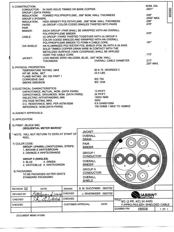
Our blue cable is a halogen-free solid-wire modified CAT-5 cable, part number 08508 designed by Quabbin Wire and Cable for the LWDAQ. The blue cable is faster on its two twisted pairs than the white cable, and offers less resistance. But it offers only two twisted pairs instead of the CAT-5 specification's four twisted pairs. The LWDAQ needs only two twisted pairs. The remaining four wires it uses for power.
| Manufacturer Part Number | 08508 |
| Manufacturer | Quabbin Wire and Cable |
| Conductor | solid copper |
| Insulation | foam polypropylene |
| Shield | aluminized polyester foil |
| Drain Wire | 24 AWG solid tinned |
| Jacket Diameter | 5.6 mm max |
| Jacket | low-smoke zero halogen |
| Operating Temperature | 60 C max |
| Approximate Price in 2016 | 1.50 $/m |
| Mass | 39 g/m |
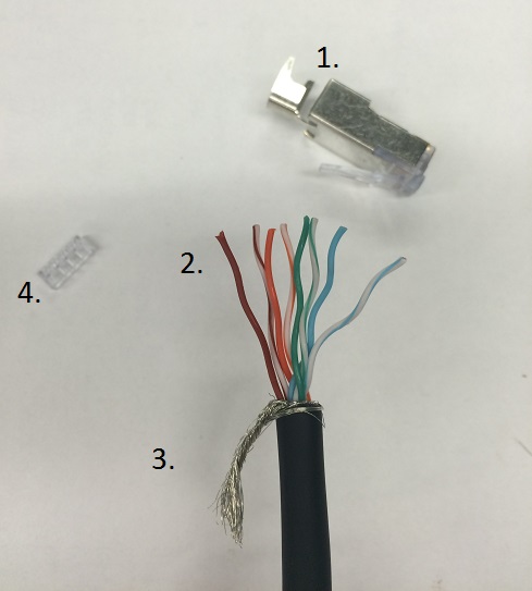
The stranded-wire and solid-wire use the same connector. This connector comes with an attached strain relief. The strain relief holds the cable jacket firmly, and presses against the cable's drain wire, so that we have reliable connection between the cable shield and the connector shield. The connector also comes with a load bar, shown as number 4 here. The load bar makes it easier to prepare the wires for insertion into the connector. We recommend that the load bar is used for the production of black cables and not blue cables, but since the connector comes with the load bar you may still choose to use it for blue cables as well.
| Manufacturer Part Number | 0449150021 |
| Manufacturer | Molex |
| Description | modular plug, shielded, 8-way, with load bar. |
| For Cable Type | round cable |
| For Conductor Type | stranded or solid wire |
| Approximate Price in 2016 | $2 each |
Note that the black cable is fully CAT-5, and you can use it to make Ethernet cables according to the industry-standard Ethernet color codes and pinouts. But the blue cable is a modified CAT-5 cable. You can make an Ethernet cable with our blue cable, but you need to use a modified color code, as we explain below.
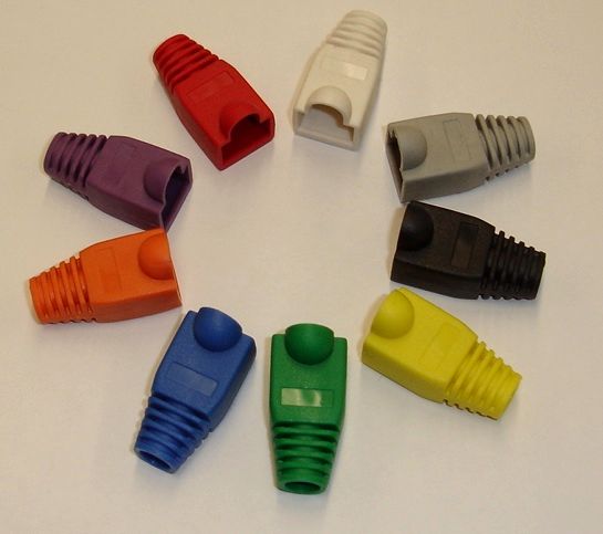
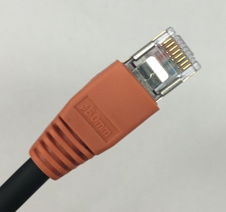
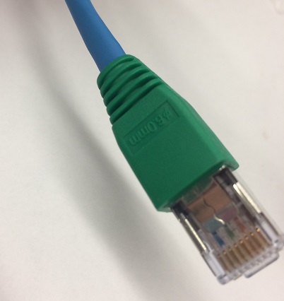
The above figure shows the various colors of connector boots we use LWDAQ cables. The cable openings on our boots have a diameter of 6.0 mm. All our boots provide a protective cover for the connector locking tab. The cover allows you to drag the cable across the floor and through apertures without worrying about snapping the tab off. The cover unfortunately also makes it more difficult to press the locking tab down to release the connector. We tried boots without the protective cover, and they are easier to use when you are plugging in and unplugging the connector frequently. But it is easy enough to cut the protective cover off the boot with a razor blade for those cables that you are frequently unplugging. So we settled in the end upon boots with the protective cover. The boots provide a small flat space on one side in which you can write a number to distinguish between cables with the same boot color.
[29-JAN-26] Our cable-making kit contains the following.
To make cables according to our instructions, you will need a scalpel, wire cutters, a loupe, and a bright lamp. It is possible that you may have parts from old kits, including a white stranded cable and connectors without strain relief attached. If you have these parts, see our LWDAQ Archive for assembly instructions.
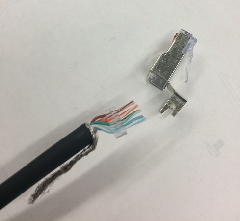
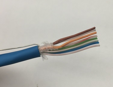
[29-JAN-26] The figure below shows the end of a cable with about 25 mm of jacket and shield removed. The individual conductors are separated and arranged in the order in which they must be inserted into the connector. A clear plastic loadbar comes with the connector to hold the wires while we insert them into the connector. The boot is already on the cable out of sight. The drain wire, which provides electrical connection to the shield, is twisted together and pushed to the side. Your first step in making a cable is to push the plastic boot onto the cable. There is no way to put the boot on after you have attached the connectors.
Remove 25 mm of jacket from the end of the cable. Cut around the cable with a scalpel, bend the jacket at the cut a couple of times, and pull the jacket off over the end of the cable. You do not have to worry too much about cutting the conductors, because the shield protects them. Don't cut so hard that you pass through the shield and cut the wire insulation. With the jacket removed from the end of the cable, you will encounter the drain wire. The drain wire is stranded. Unwrap the drain wire from the cable and twist it around itself. The drain wire is connected to the shield inside the cable. Fold the twisted drain wires back and keep it out of the way until crimping the strain relief.
Tear off the foil shield. You probably scratched it already with the scalpel when removing the jacket, so it should tear easily. If not, cut it off with your wire cutters. Remove the transparent binder around the wires as well, which you might also have to cut with your wire cutters. Study the wire insulation where you made your scalpel cut, looking for nicks. If you see any, cut the cable back and start again.
Separate the wires of each twisted pair by inserting your nail or a screwdriver in between the wires near the jacket, and pulling out to the end of the pair. Straighten the wires as best you can, and arrange them in the correct order, as shown above. From left to right, the order is brown, brown-and-white, orange, orange-and-white, green, green-and-white, blue, then finally blue-and-white. Insert each wire one at a time into the load bar. There is a seperate hole for each wire, and the holes are small and long enough that inserting the wires all at once is difficult. The load bar is symmetric: so as long as the colors are in order it does not matter from which side you start. When all wires are inserted into the load bar, cut the wires so that they are even and square-cut at the ends. The total length of the wires between the ends and the jacket should now be about 15 mm.
Straigten the wires as much as possible. Bends in the wires make it more likely that the wires will get stuck inside the connector and not fully reach the end. Despite the staggered pattern of both the load bar and the final position of the wires in the connector, the wires must be organised into a straight line before insertion into the connector.
Fold back the strain relief attatched to the connector. Hold the connector with the locking tab down, and hold the cable with the open face of the load bar on the top. The brown wire must be on the left, and the blue-and-white wire must be on the right as you look into the open side of the connector. The twisted drain wire should be folded down and out of the way. Push the load bar into the aperture at the base of the connector. As the jacket begins to enter the connector, you may feel some resistance. Ease the cable into the connector, and pay attention to whether the wires are able to slide cleanly into their slots or if they are hitting a wall. Do not push hard until it is clear that each wire has found its place. Once this happens, force the cable farther inside. When it stops, push harder and move the cable back and forth, to work the wires down to the very end of the connector. Make sure the black jacket enters the base of the connector. Push until the black jacket will not go any farther. The transparent end of the connector should look like the photograph below.
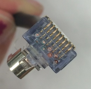
With your bright light and magnifying glass, examine the end of the connector. You should see eight wires with their stranded conductors sparkling in the light pressed up against the transparent end wall of the connector housing. Also, inspect the wires through the sides of the connector. Using the magnifying glass, you should see that all wires are pressed firmly against the end. If the wires are there, you will see each of them clearly, and you can be sure that you are ready to crimp the connector. If you cannot see all eight wires clearly through the end wall of the connector, pull out the wires and the load bar and try again. It is possible that the wires have become too bent to properly reach the end of the connector. You may need to use your fingers or pliers to straighten them out. Be sure the wires remain in the correct order.
Assuming all the wires are visible and in their proper places, you are ready to crimp. Be sure that the strain relief will not be in the way of the crimper when the connector is inserted. Push the connector into the modular crimping tool as show below and squeeze the tool's crimping arms together. You should hear a snapping noise to indicate that the crimp is finished. This is the sound of the jacket restraint inside the connector snapping into place. Take the connector out of the tool. You may need to press down the locking tab on the connector in order to get the connector out of the crimper. Looking in the open end of the connector, you should see that the jacket restraint has been forced down into the jacket, holding it in place.
Check that all eight crimp terminals are pressed down into the connector. None of the crimp terminals should stick out above the plastic ridges that separate them. The jacket restraint holds the jacket in place, but we would like additional strain relief on the cable to stop the cable becoming loose in the connector. Furthermore, we have not yet made reliable contact between the connector and cable shields. The strain relief attached to the connector solves both these problems for us. It holds the cable firmly and grabs onto the cable's drain wire to make the connection between the cable and connector shield. Pull back the strain relief back so it touches the cable jacket. Fold the arms of the strain relief around both the cable jacket and the drain wire. If the strain relief arms are not folded around the wire, they may be pushed in the opposite direction when you crimp the strain relief.
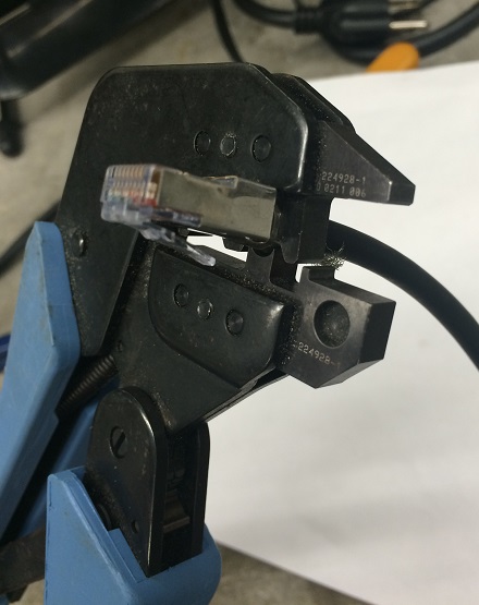
You may crimp the strain relief either with pliers, or a crimp tool with the right size aperture, or with a special strain relief crimp tool. The photograph below shows the special strain relief crimp tool we like to use, but this tool is no longer being manufactured. If you have a crimp tool that will work with the strain relief, insert the strain relief into the crimper. Use the circular set of teeth farthest from the handle. Press firmly until you hear a click and the crimper releases. The strain relief should now be fixed firmly in place. Trim the drain wire and push the connector boot up over the base of the connector. The finished product looks like the photograph below.
To complete your cable, put a connector on the other end as well. Remember to put the boot on before beginning to attach the connector. Measure the length of the cable and add 20 mm to the required length before cutting the cable. Now remove the final twenty millimeters of jacket, and you will end up, after following the procedure given above, with a cable of the correct length, give or take a few millimeters.
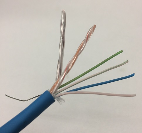
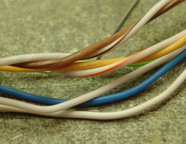
[29-JAN-26] Remove 25 mm of the blue cable jacket in the same way as the black cable. There is a foil shield inside, but usually this comes off with the jacket. Inside you will find a solid drain wire and all other wires wrapped in plastic. Bend the drain wire out of the way before removing the plastic. The figure below shows the wires of a blue cable exposed after the jacket and shield have been cut back. You will notice that the brown and the orange twisted pairs are wrapped in their own transparent plastic binder. You must un-wrap this binder before you can separate the wires as shown in above.
The blue cable conductors are solid copper, so they are stiffer. This means that they are more difficult to straighten out, but they are easier to push into the connector. You can build a blue cable with or without a load bar. Load bars are useful in keeping the wires in order inside the connector, but the solid wires are stiff enough that they are not necessary. Follow the same procedure as you would for black cables, with the following changes:
When you make root cables, be sure that you are using the solid-wire connectors, not the stranded-wire connectors. If you use the stranded-wire connectors, the teeth of the connector contacts will attempt to cut through the center of the solid wires, and when they fail to do so, they will pass to one side, and the contact between them and the wire will be unreliable. In a few years, oxide will build up on the copper and contact will be intermittent.
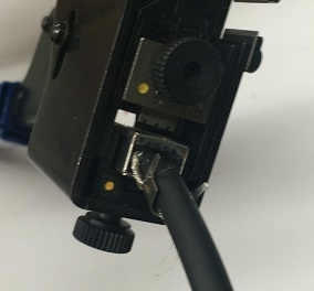
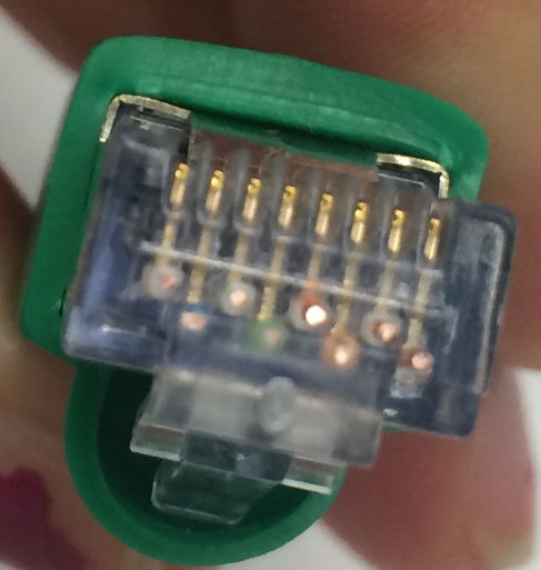
[29-JAN-26] You may find that you don't have space adjacent to your LWDAQ device for a strain relief and a connector boot. In that case, you can sacrifice shielding and toughness for a smaller connector. The figure below shows our cut-off, unshielded modular plug that is part of a low-profile cable. You make one of cutt-off plugs by cutting off the jacket-crimping part of an unshielded modular connector like the 940-SP-3088R from Steward Connector. The jacket-crimping part is the rear 11 mm. We made our cut-off plugs on a band saw, where we were able to cut three per minute without hurrying. At first, we cut off the connector's release tab along with the connector body, but after complaints from our users we started leaving the tab intact.
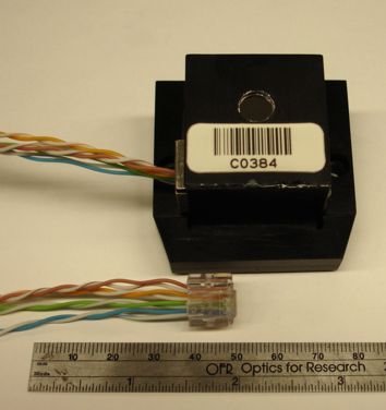
To make the low-profile cable, you strip the jacket and shield from the cable, add a cut-off plug to one end, and an ordinary unshielded plug to the other. Removing the jacket and shield allows you to get the wires through tight spaces. We forsee no problems with cables like these up to 100 cm long. If you are going to make them longer than that, we suggest you try the cables in their final environment, so you can see if they contaminate other instruments with broadcast noise, or if the LWDAQ signals are themselves contaminated. To keep the unshielded cables short, you can use an RJ-45 union 50 cm to 100 cm from the cut-off plug. If you use a shielded metal union, you can connect the union housing to your local ground, so that the shield leading to the union will operate properly.
Out of ten low-profile cables we made, three did not work. We had to replace the cut-off connector because we had not crimped it properly. Crimping the cut-off connector takes some care, because crimpers like the one we recommend above use the rear end of the plug to stop you from pushing the plug too far into the crimper. The cut-off plug has no rear, and so you must be careful not to push it in too far. Once we discovered this problem, we were able to crimp the cut-off connectors reliably.
Our chief concern with these low-profile cables is not noise, signal integrity, and cross-talk, but rather the mechanical integrity of the connectors. The wires are held in place each by their own contact crimp. There is no other strain relief. We recommend adding a cable tie around the twisted pair bundles, about 10 cm from each connector. This helps spread cable strain across the eight wire crimps. Another way to make the low-profile cable more rugged is to leave the jacket on for most of the length of the cable, as shown above. This hybrid low-profile cable is 100 cm long, with the final 20 cm bare of jacket and shield.
[29-JAN-26] We do not provide a special test circuit for cables. We thought about designing one, but testing the high-frequency properties of the cable is difficult. Ethernet cable test devices can cost up to a thousand dollars. So in the end we decided to use what you have already on hand: the LWDAQ and a voltmeter. Testing a cable with the LWDAQ is a four-step process. You will need a LWDAQ with an analog image sensor of some variety, like the Inplane Image Sensor (A2036), the Camera (A2056), or a BCAM Head (A2048). We know of no cable errors that will remain undetected by all four of these tests, but all tests are necessary.
[24-MAY-21] Our recommended minimum bending radius for solid-conductor LWDAQ cables is 5 cm, and for stranded-conductor LWDAQ cables is 2 cm. Our blue cable is solid-conductor. Our white and black cables are stranded-conductor. These recommendations are conservative in that we know perfectly well that the cable can survive sharper bends. But cable-routers often ask for a specification they can follow, and the above radii are certain to cause no problems.
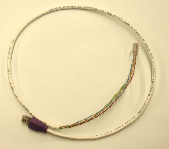
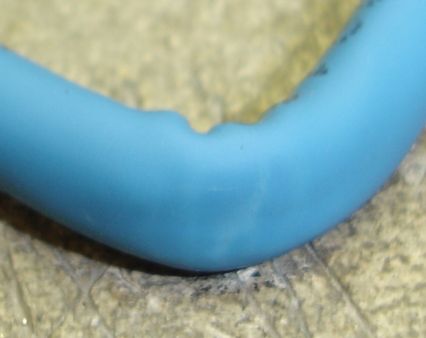
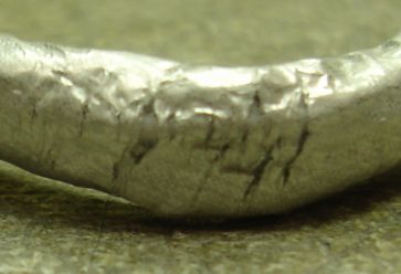
The black cable is flexible: we can bend it back upon itself many times without seeing any effect upon the jacket, shield, or conductors. But the blue cable is much more stiff, on account of its solid-wire conductors. The halogen-free jacket is not as resiliant as a halogenated jacket. The result is a cable that can become disfigured after repeated right-angle bending. As Alex Asen reporst, "I bent the blue cable back and forth at a right angle twenty times. After the test, the jacket is slightly discolored, turning from blue to white. The photograph accurately reflects the amount of discoloration. The bending test caused several breaks in the aluminum foil shielding. The foil, however, has a thin plastic backing that prevent it from tearing completely through. The plastic backing remained completely intact even in place where the foil broke. No single tear in the foil runs the entire width of the foil, so the electrical continuity of the shielding was not broken. Although it appears that a great number of bends would eventually break the continuity of the foil, after twenty bends there is no single gap larger than half the width of the foil. There is no visible damage to any of the wires inside the shielding and all passed testing with the cable tester."
We have the following report from Anatoli Kozhin, which appears to agree with Alex's findings. "It was the simplest test, I have bended (90 degrees, about 0.5-1cm of radius) the cable few times in one place, check its integrity by the cable-tester, then opened the jacket and looked at the shielding aluminium foil. The foil was locally destroyed, The jacket was not destroyed, only slightly changed colour (became white) in place of bending."
[29-JAN-26] The table below gives the pinout for a straight-through Ethernet cable. LWDAQ and Ethernet cables look the same. They use CAT-5 cable and have eight-way modular connectors on either end. You can use one type of cable in the place of another. In particular, you can buy commercial network cables up to 10 m long and use them in your laboratory LWDAQ.
| Pin | Signal | Wire Color | Description |
| 1 | T+ | Orange and White | LVD Transmit Positive |
| 2 | T- | Orange | LVS Transmit Negative |
| 3 | R+ | Green and White | LVD Receive Positive |
| 4 | NC | Blue | Unused |
| 5 | NC | Blue and White | Unused |
| 6 | R- | Green | LVD Receive Negative |
| 7 | NC | Brown and White | Unused |
| 8 | NC | Brown | Unused |
The first thing to note about the straight-through Ethernet cable is that it connects precisely the same pins on its connectors as would a LWDAQ cable. One difference is that pins 3 and 4 pass share a twisted pair of wires in the LWDAQ cable, but not so in the Ethernet cable. Conversely, pins 3 and 6 share a twisted pair of wires in the Ethernet cable, but not so in the LWDAQ cable. This difference between the two cables has no effect upon their behavior at lengths of a few meters. The color coding is different of the two cables is different, too, but this does not affect short cables either.
Claim: LWDAQ and Straight-Through Ethernet cables are interchangeable for lengths up to a few meters.
Let us consider what happens if we use a long straight-through Ethernet cable as a LWDAQ cable. The LWDAQ's T+ and T- LVDS (low voltage differential signal) propagates along the twisted pair of wires with colors orange-and-white and orange respectively. The R+ and R- lines do not propagate down a twisted pair. The high-frequency components of the signal recovered by the driver at the end of a long cable will be attenuated. If the signal returned from the LWDAQ device is 2-MHz analog data, such as that returned from a BCAM Head (A2051), or low-frequency measurements such as those from the RTD Head (A2053), this high-frequency attenuation will be of no consequence. But if the device is transmitting logic signals with 50-ns pulses, as some of our future devices will do, the returned signal might be unusable.
Claim: Any Straight-Through Ethernet cable up to 10 m long can be used as an LWDAQ Cable.
If we use a LWDAQ cable as an Ethernet cable, the Ethernet R+ and R- signals don't get passed along a twisted pair of wires. Our experience is that a ten-meter blue LWDAQ cable will work for 10-Base-T but not 100-Base-T. A five-meter black LWDAQ cable will also work for 10-Base-T but not 100-Bast-T. You might hope that your computer will auto-negotiate 10-Base-T instead of 100-Base-T when it is communicating across such a cable, but that is not what happens. Instead, the computer selects 100-Base-T any time the device at the other end supports 100-Base-T, and then the communication is slow because of packet loss.
One final thing we might worry about is, "What happens if we connect a LWDAQ socket to an Ethernet socket?" If you look at the two cable pin-outs, you will see that the LWDAQ connects no power to any of the Ethernet signal pins, so no damage will occur to either device.
Claim: No harm will come to either device if we connect any LWDAQ socket to any un-powered Etherenet socket.
We say un-powered because sometimes networks, especially Ethernet-based phone networks, use the four free wires on the Ethernet cable to carry power for Ethernet devices. If power is carried on these pins, it might blow the LWDAQ R+ input. The power supplies themselves will conflict with one another, and both are, presumable, protected against short circuits.
Claim: No harm will come to a powered Ethernet socket if you plug it into any LWDAQ socket.
Claim: You might damage the LVDS R+ input on a LWDAQ Multiplexer or LWDAQ Device if you plug either into a powered Ethernet socket.
If you use our blue cable to make a straight-through Ethernet cable, then you should change the color code of the Ethernet cable. Use the brown-white and brown wires for R+ and R-. If you use the usual Ethernet colors, Ethernet R+ and R- will not be twisted together, and the cable will attenuate a 100-Base-T signal.
Warning: Gigabit cross-over cables destroy LWDAQ devices.
Now let us consider Ethernet cross-over cables. The 10-Base-T and 100-Base-T cross-over cables exchange pins 1 and 2 with pins 3 and 6, but are otherwise the same as straight-through cables. A LWDAQ device will not work with such a cross-over cable, but neither will it suffer any damage. The same is not true for 1000-Base-T (gigabit) cross-over cables. These switch all the remaining pins around as well, and connect power in reverse to the LWDAQ device. The cable destroys our device. In the case of several A2051 devices connected with a gigabit cross-over cable, all seven logic chips on the board were destroyed.