 Electromyogram
| Introduction |
| Downloads |
| EMG Only |
| iEEG with EMG |
| Sleep Scoring |
[27-JUL-26] This page is a record of our study of electromyogram (EMG) recording in mice and rats. We are, of course, using our own implantable telemetry sensors to make these recordings, and we are working with Avastus Preclinical Services locally, and with collaborators abroad, to obtain the recordings. Our primary objective with EMG recordings is to obtain reliable amplitude to distinguish between sleep and wake. Having established that we can use EMG to distinguish waking from sleeping, we move on to recording iEEG and EMG simultaneously and scoring eight-second intervals for NREM, REM, and Wake.
Our implantable telemetry sensors are equipped with flexible, silicone-insulated leads. We can prepare the ends of the leads in any number of ways so as to obtain a secure connection to our recording target. When recording EMG, our target is always a muscle. We plan to use our "soft tissue electrode" for EMG, which we call our "S-Coil". For iEEG recording, we will use an "A-Coil" to make a "bare wire electrode" that we hold in a skull hole with a screw.
[27-JUL-26] A repository of recordings and characteristics files. We provide example hour-long raw data files in NDF format, and larger sets of processed data in text files.
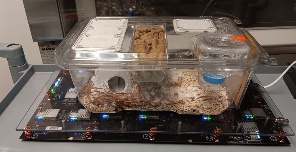
[07-MAY-26] We have one hundred hours of EMG recorded from four mice with A3048S2-SS SCTs. The recordings were performed at a local contract research organisation with whom we are collaborating. All surgeries and housing performed in compliance with local regulations at Avastus Preclinical Services. All four SCTs are equipped with C-Leads terminated with S-Coils. Devices No117 and No121 were implanted first, with 50-mm leads. Devices No11 and No12 were implanted several days later, observed by us, and have 35-mm leads. Telemetry reception in the CRO laboratory is perfect without a Faraday enclosure. We place the cage with four mice on an A3038C Animal Location Tracker (ALT).
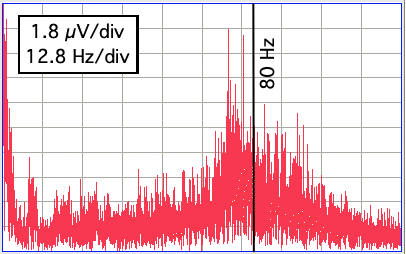
We process the recordings in eight-second intervals, using the ALT position measurements to obtain the average speed of the animals in centimeters per second for each interval, and using the telemetry signals to obtain the root mean square amplitude of each signal in the band 40-120 Hz. We select this band after observing that the waking EMG power starts to rise at about 40 Hz and starts to roll off at 80 Hz. The 80-Hz roll-off is due to the 80-Hz low-pass filter in the A3048S2. The 40-Hz rise is a feature of the EMG in all four animals.
No117 electrodes in left and right nuchal muscles. This signal has amplitude 6-60 μV including intermittent ECG pulses of amplitude 200 μVpp, often far larger than other variations in the signal. Because these pulses are intermittent, we cannot remove them to expose what we hope to be underlying EMG. We note, however, that the intermittent ECG seems often to vanish when the animal is stationary, allowing the signal amplitude to drop as low as 6 μV. No121 electrodes are implanted side by side in the left nuchal muscle. This signal sometimes contains traces of ECG, but the pulses are never more than 20 μVpp and never contribute significantly to the rms amplitude, which varies from 4-40 μV rms. The amplitude is almost always above 10 μV rms when the animal moves more than 10 cm/s. When the animal activity is 0-2 cm/s the signal amplitude is either 12 μV or 5 μV. We believe this is EMG, showing activity, waking, and sleeping.
Of the No11 and No12 transmitters, one has both leads implanted in the left nuchal muscle, the other has one in the left and one in the right, but we don't yet know which. Neither signal contains significant ECG in the beginning, but as the recording progresses, we see more and more large spikes on the No11 recording. Signal amplitude varies 4-40 μV, with No12 showing some peaks of 60 μVpp. As with No121, amplitude is greater than 10 μV when the animal is moving around, and is 4-12 μV when it is stationary. We have strong, intermittent ECG is to our EMG recording from SCT No117. In the figure below we show an example of No117 with ECG compared to No121 without ECG when both animals are active at 4 cm/s in a one-second interval.
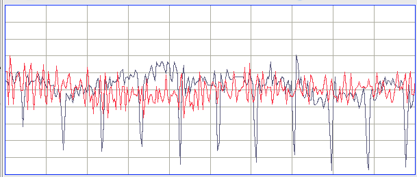
Looking at longer periods of ECG and activity measured in eight-second intervals, we see in the recording from No117 spikes during inactive periods that we don't see in the signal from No121. These spikes correlate with periods in which ECG enters the signal and increases its amplitude. They occur more often when the animal is inactive and awake, but sometimes when the animal is inactive and asleep. We conclude that intermittent ECG undermines our sleep scoring, but does not render the scoring completely inaccurate, because the apparent waking of the animal due to the arrival of ECG in otherwise low-amplitude EMG is rare.
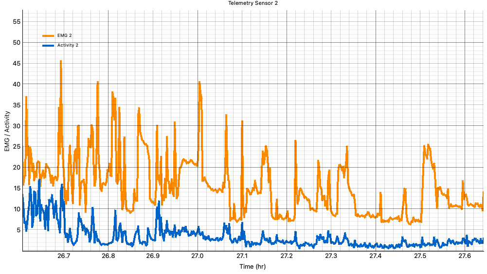
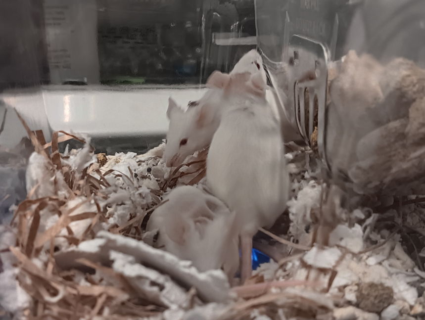
[12-MAY-26] One of the four mice died last week, the one with the No11 SCT. The other three appear healthy and active, see video below. We transfer seven days of EMG recordings. Initial examination shows no loss of amplitude in the active EMG, and no invation of ECG.
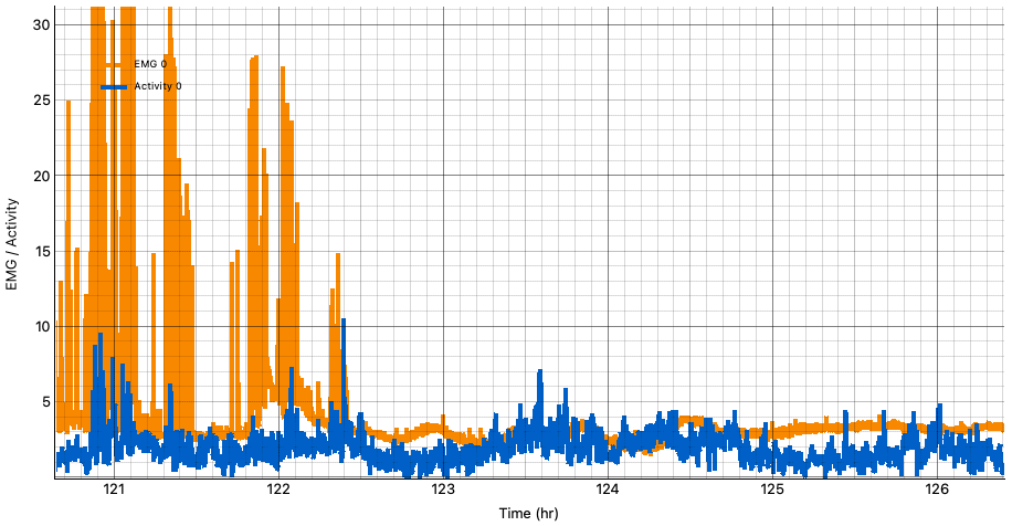
[13-MAY-26] One of the four mice died in the past week, No11. This signal showed larger and more frequent non-EMG spikes as the days went by, until in hour 122 of our study period, the EMG and activity drop down to below sleep levels. This is the moment the animal died. Thereafter, EMG power is 2-4 μV rms and activity is 1-3 cm/s. These two values obtained from a dead animal give us our noise floor for both EMG and activity recording. Even if the body generates not signal, the transmitter and small local movements combine to generate a singal of up to 4 μV amplitude, and movement of the other animals around and about the dead animal generate apparent activity of up to 3 cm/s.
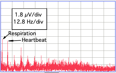
We have been band-pass filtering our EMG to 40-120 Hz before calculating amplitude. The spectrum of our waking EMG starts to rise at about 50 Hz and then starts to fall at 80 Hz, which is the corner frequency of the A3048S2's low-pass filter. We imaging that if we were to remove this filter, and instead let the amplifier deliver gain up to the limit of its operational amplifiers, which is about 600 Hz, we would see significantly more EMG power, although we are not sure how much more: perhaps double the amplitude. We would not be sampling fast enough to see 300-Hz oscillations, but we would be sampling fast enough to measure the amplitude of 40-600 Hz oscillations. We note that in the sleeping EMG, the amplitude drops so low that we can see, below 30 Hz, the fundamental and harmonic of ECG, as well as the fundamental of respiration.
[08-JUN-26] We are examining archives M1771236143.ndf (16-FEB-26, No7, No18, and No113) and M1771416228.ndf (18-FEB-26, No118, No185, and No197) received from AMU. Each archive contains signals from three A3047A3D-C transmitters implanted in three separate rats and recorded by an Animal Location Tracker (ALT). Each transmitter provides EMG 128 SPS 2-80 Hz 30 mV, ECG 256 SPS 2-80 Hz 60 mV, EGG 64 SPS 0-20 Hz 120 mV, EEG 512 SPS 0-160 Hz 120 mV, Temperature 64 SPS. The ALT provides activity in centimeters moved per second. In M1771236143.ndf we have three EMG signals: No7, No18, and No113. We plot EMG amplitude 40-120 Hz and activity in cm/s for each of these.
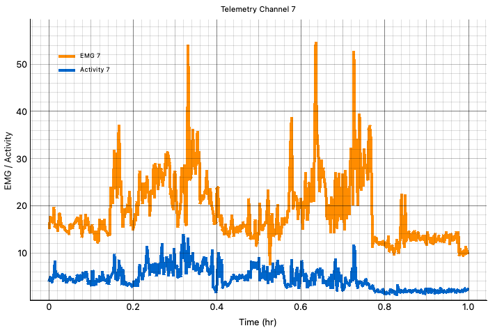
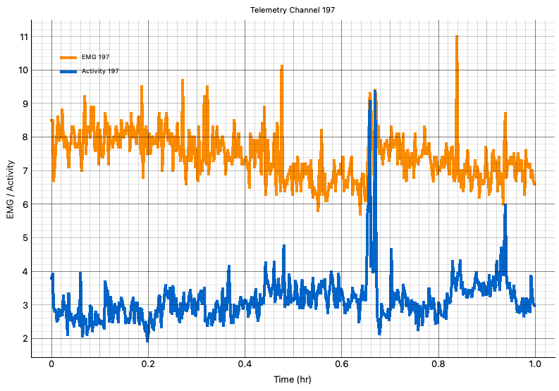
In M1771416228.ndf, we have three EMG signals: No118, No185, and No197. In No118 and No185 we see ECG of up to 500 μVpp corrupting the EMG signal. The ECG amplitude varies. It may correlate with activity, but we do not investigate further. In No197 we see no ECG. We plot amplitude and activity, see M1771416228_No197. The EMG amplitude is almost always 6-7 μV rms. Activity is 3-4 cm/s, which we associate with resting or sleeping, except for one brief period of 9 cm/s. It could be that this animal is resting the entire time, and the 9 cm/s is a measurement error caused by another animal moving close to or on top of the resting animal.
[13-JUN-26] We have 96 hours recorded from two A3049J2S Subcutaneous Transmitters, No163 and No195, implanted in two mice by our local collaborator. Each transmitter provides four leads. Two for recording iEEG and two for EMG. The EMG electrodes are S-Coils fastened on opposite nuchal muscles near the skull. The iEEG electrodes are A-Coils held in burr holes by L-Screws. The leads are too long for this procedure: the surgeon had to coil them to fit them under the skin.
We process the 96 hours to obtain delta amplitude (1-4 Hz), EMG amplitude (4-120 Hz), and activity (cm/s) in eight-second intervals using our Activity and Circadian Rhythm Processor, ACRP1R1.tcl

We are already confident that we can detect sleep with low amplitude in the EMG signal. Now we are looking to distinguish between NREM and REM sleep using the power in the 1-4 Hz delta band. The delta band is reputed to contain more power during NREM. So we are looking at the sleeping periods to see if we have a transition between two distinct delta-band amplitudes.
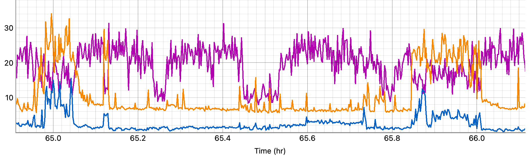
Sometimes, the distinction between NREM and REM from delta amplitude is obvious, as in our example "REM and NREM Distinguished by Delta Amplitude". Other times, the distinction is less obvious. We find in No163 some beautiful examples of sustained sinusoidal spindles during sleep, with frequency 6-8 Hz. According to the literature, as surveyed by ChatGPT, these sustained spindles are a sign of REM sleep, not NREM. We re-process the data, now calculating amplitude in the delta 0.5-4 Hz, theta 6-10 Hz, and sigma 11-16 Hz bands, so we can investigate if the relative amplitudes in these bands is a reliable indicator for NREM and REM. We re-process the 96 hours so as to produce the amplitude in these bands.
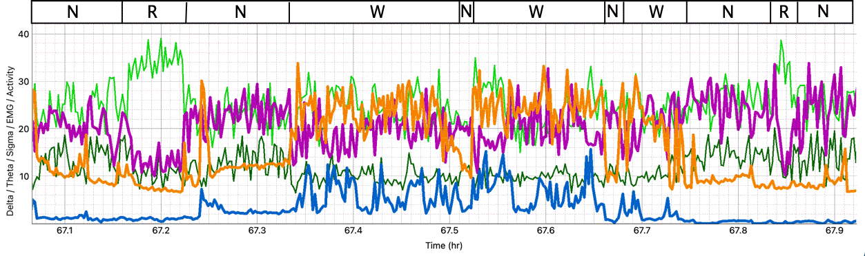
We pick hour 67 of No195 to illustrate what we propose to be the three stages of sleep: NREM, REM, and Wake. In this hour, we have a period of sleep in which delta power drops and theta power rises. We open the archive for hour 67, M1780928425.zip, and go to time 714 s. We view an eight-second interval and see sustained 150-μVpp spindles at 8 Hz.
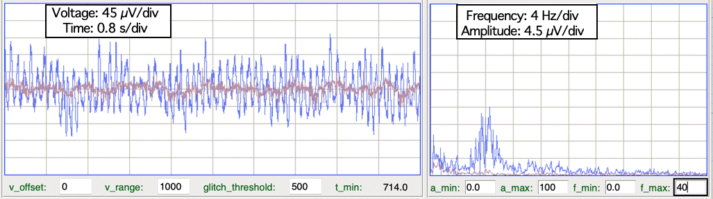
Sustained spindles in the range 6-10 Hz we believe to be a sign of REM sleep. The slow waves in the range 0.5-4 Hz we see in NREM are accompanied by bursts of spindles, but not sustained spindles. When we see delta amplitude drop during sleep, we always see theta amplitude rising. These periods we score as REM. When delta amplitude is high during sleep, we score as NREM. The rest is WAKE.
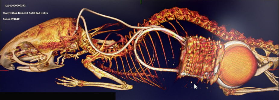
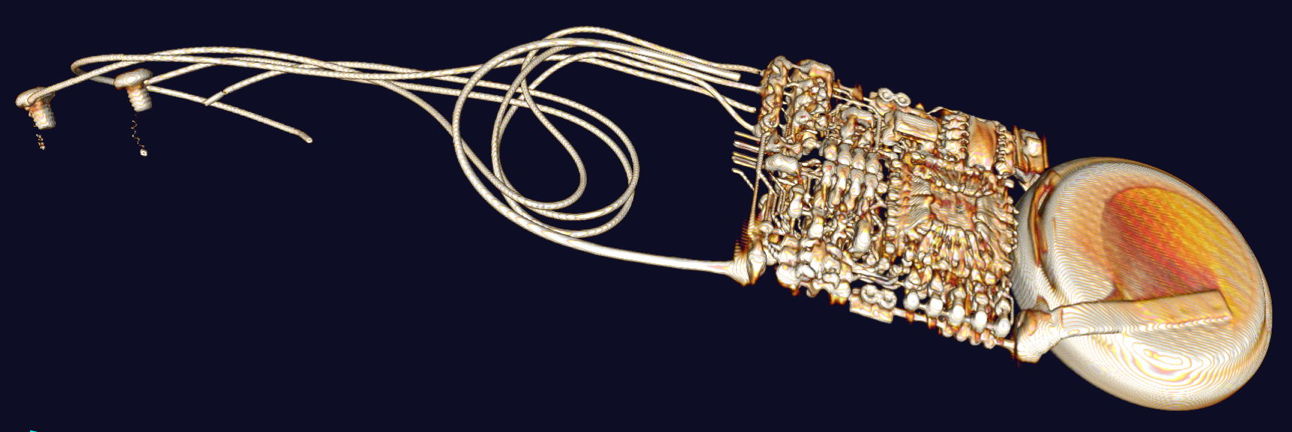
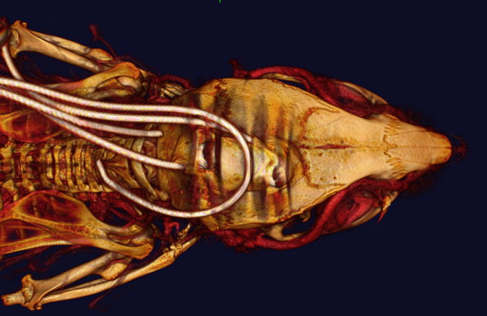
[28-JUL-26] We have 490 hours of iEEG and EMG recorded simultaneously from two separate mice. The channel numbers are No163 iEEG, No164 EMG in first mouse, and No195 iEEG, No196 EMG in second mouse. We will refer to the mice as No163 and No195. A problem arises with the iEEG electrodes at about hour 400 in No163, leading to massive artifact and loss of iEEG. One of the electrodes came loose. The X-Ray image below is of animal No195 after the end of the experiment, showing the iEEG and EMG leads.
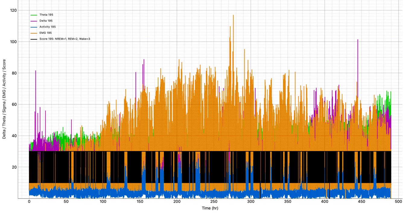
In the figure below we show the entire 490 hours of delta amplitude, theta amplitude, EMG amplitude, ALT-measured activity, and overlayed sleep score. We will explain how we obtained the sleep score in the paragraphs below. The delta, theta, EMG, and activity measurements we obtained with our Activity and Circadian Rhythm Processor, ACRP1R1.tcl. We see a clear circadian rhythm in the black sleep scoring line.
To perform sleep scoring, we use our Event Classifier, which is a component of our Neuroplayer Tool. We prepare a Sleep Scoring Processor, SSP1R1.tcl. This processor produces the same delta, theta, EMG and activity measurements as our ACRP1 processor, but adds a delta-theta amplitude ratio as well. Each of these measurements the processor transforms into a sigmoidal metric between zero and one for use in the Event Classifier, which performs classification based upon proximity of intervals as they appear embedded in the metric space. We now proceed through the recordings from both animals and build up a library of examples of NREM, REM, and Wake intervals that we identify to our own satisfaction by examining the signals themselves as well as all the measurements. The figure below shows how this library appears in the Event Classifier view when plotted as EMG power metric and delta-theta ratio metric.
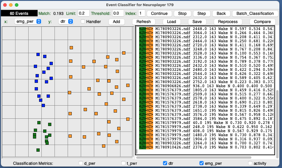
It is clear that our classification could take place by means of a threshold in EMG power metric to distinguish sleep from wake, and another threshold in delta-theta ratio metric to distinguish NREM from REM. But we use the Event Classifier to perform the classification because it provides a built in Batch Classifier that will write a big file full of the classifications to disk. To perform the classification, however, we need first to calculate the metrics for every interval, which we do by applying the SSP1 processor to the 490 hours of recordings. We then apply the Batch Classifier asking it to classify every interval for No163, and then later for No195. We get two files Score_163.txt and Score_195.txt. We turn the score into its own plot: NREM is 10, REM is 20, and Wake is 30. We plot delta amplitude, theta amplitude, EMG amplitude, and activity along with our scoring line. To perform the plot we use plot_acrp.py, which reads the earlier ACRP1 metrics and the scoring file and combines them into one plot. You can download all the characteristics files, library, scoring, and plotting programs in one archive SS_Demo.zip.
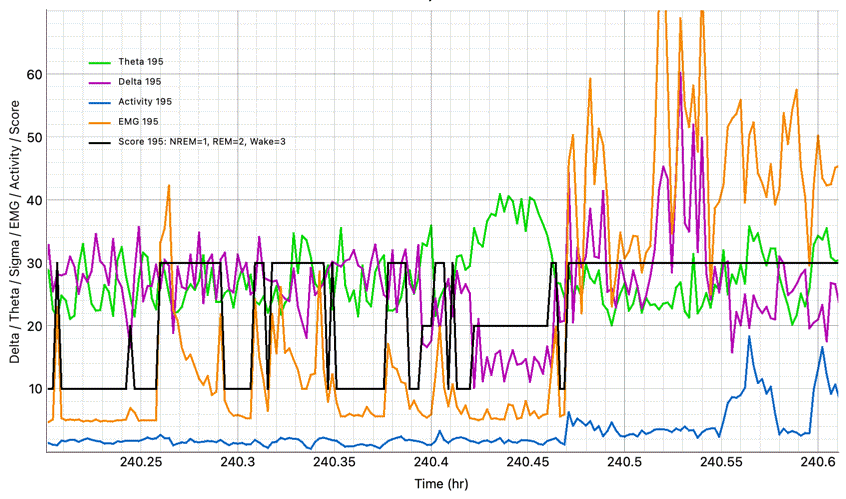
So far as we can tell, the scoring works well and consistently throughout the recording from both animals, with the exception of the final 100 hours from No163, where the iEEG recording fails. In the above figure we see a clear period of REM sleep. In the figure below we see an active period with sleep on either side.
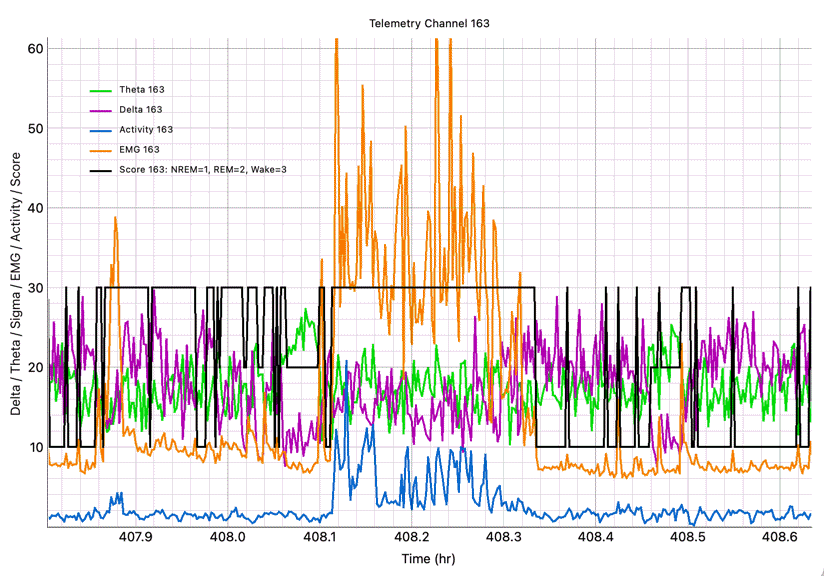
One of our concerns is whether or not the EMG amplitude corresponding to sleep will remain the same throughout, and between the two animals, and indeed it seems to: anything below 9 μV and below appears to be sleep throughout and for both.
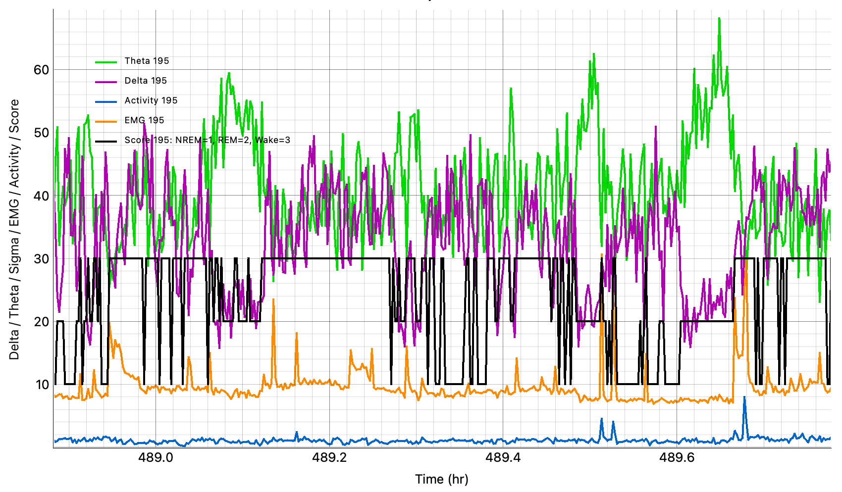
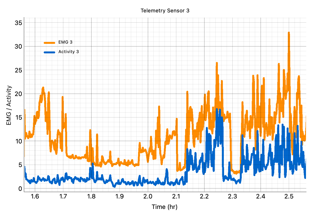
As with our EMG-only recordings, we never see EMG of sleep-level amplitude combined with ALT-measured movement-level activity. Any time the ALT says the animal is moving around, the EMG amplitude is high.
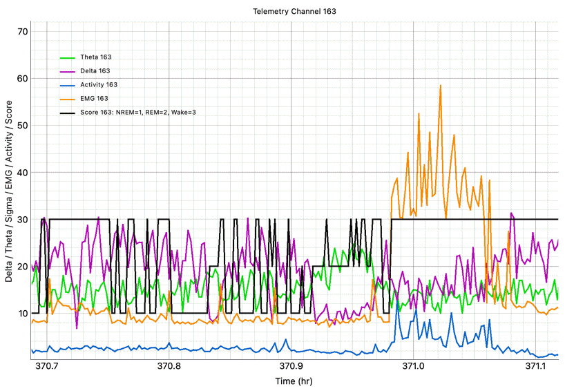
The scoring contains changes from one interval to the next, but overall, it seems to follow a circadian rhythm and behave well. We see no significant deviation by the scoring from what we would just the score to be by examining the data ourselves.