| Description |
| Versions |
| Analog Inputs |
| Operation |
| Design |
Note: The A3054 is currently in development. This manual is a preview of what we hope to release for implantation testing July 2026.
[29-JUN-26] The A3054 Intraperitoneal Transmitter (IPT) is an encapsulated telemetry sensor designed for implantation in the peritoneal cavity of a mouse or a rat. The A3054 provides three unipolar inputs that share the same reference potential, a single bipolar, an accelerometer, and a thermometer. Its pill-shaped, silicone-coated body provides two stainless steel suture loops to hold it in place within the peritoneal cavity of a mouse or rat. The A3054 wakes up with a brief application of a magnetic field. It goes to sleep again with another brief application of a magnetic field. The A3054 can programmed to tansmit any combination of measurements from its available sensors. We call this configuration of measurements and transmission the telemetry protocol. The first programming of the device takes place during manufacturing, and this original telemetry protocol will come into effect when we wake up the device. The protocol is stored in the device's non-volatile memory, and so is persistent from one waking period to the next. We can upload a new protocol at any time, because the A3054 is not only a transmitter of telemetry signals, but also a receiver of wireless commands. We upload a new protocol to the A3054's non-volatile memory, reboot the A3054 with a wireless command or by applying a magnet, and the new protocol will come into effect. The protocol will be persistent from one waking period to the next, just like the original protocol.
The A3054's three unipolar inputs can be configured collectively for AC or DC recording. When configured for AC recording, the input dynamic range is ±15 mV, and when configured for DC recording, the input dynamic range is ±56 mV. The unipolar inputs can be configured individually for transmission sample rates 0, 64, 128, 256, 512, and 1024 SPS (samples per second), for which the signal bandwidths in Hertz will be a little less than half the sample rate in SPS. These three unipolar inputs are optimized for recording intracranial electroencephalogram (iEEG), in particular for detecting seizures, inter-ictal spikes, spreading depolarization, and delta waves. The A3054's single bipolar input is always DC-coupled. It can be configured with and without digital low-pass filtering, and it can be assigned the same selection of sample rates as the unipolar inputs. The bipolar input is designed for tracing the electrocardiogram (ECG), following electrogastrogram (EGG), and measuring the amplitude of electromyogram (EMG). The A3054's accelerometer can be disabled, or it can be configured to provide a variety of acceleration measurements, ranging from an activity measurement with an update rate of 1 Hz to a three-axis acceleration measurement with an update rate of 100-Hz. The A3054's temperature sensor can be disabled, or it can be configured to provide a body temperature measurement with an update rate of 1 Hz and absolute accuracy ±0.05°C.
The A3054 provides a mechanism for measuring the impedance of its three unipolar biopotential electrodes. Upon receipt of an impedance measurement instruction from a command transmitter, the A3054 applies a voltage step to its unipolar input reference potential. Assuming the reference potential electrode is of lower impedance than the unipolar input electrode impledances, the size of the step we see on each unipolar input will be a function of its electrode impedance and the amplifier's input impedance. The A3054 can measure electrode impedance with a precision of 5 kΩ rms.
When you receive an A3054, it will be asleep. When sleeping, it consumes less than one microamp from its battery as it watches for the presence of a magnetic field. When you bring a magnet near to the sleeping A3054, it wakes up, flashes its indicator lamp, reads its telemetry protocol from its non-volatile memory, initializes itself to execute the protocol, and immediately starts executing the protocol. The telemetry protocol tells the A3054 which measurements to perform and how to transmit them. In order to program the A3054 with a new protocol we use wireless commands transmitted by a Telemetry Control Box (TCB) equipped with command transmitters, such as the A3042B-Series TCBs. The A3042A-Series TCBs do not include command transmitters, and so are not capable of re-programming an A3054. If your telemetry receivers are not equipped with command transmitters, you can order your A3054s with a telemetry protocol that suits your experiment, and so relieve yourself of the need to reprogram them at all.
| Property | Specification |
|---|---|
| Volume | 1.7±0.1 ml |
| Mass | 3.2±0.1 g |
| Operating Life | 27 days |
| Battery Capacity | 3500 μA-days |
| Shelf Life | 12 months |
| On-Off Control | magnet |
| Lead Dimensions | diameter 0.5±0.1 mm, length 50±2 mm |
| Lead Terminations | steel coil, diameter 0.25 mm, length 1.0 mm |
| Number of Inputs | 3 × unipolar, 1 × bipolar |
| Input Impedance | 1 MΩ |
| Impedance Measurement Precision | 5 kΩ |
| Sample Rate | 256 SPS each channel |
| Bandwidth | 0.0-80 Hz |
| Noise | ≤3 μV rms |
| Distortion | <0.1% |
| Dynamic Range | unipolar: &plumn;56 mV, bipolar: ±45 mV |
| Signal Bandwidth | unipolar: 0.0-100 Hz, bipolar: 0.0-100 Hz |
| Resolution | 16-bit |
| Absolute Maximum Input Voltage | ±3 V |
Each time the A3054 boots up and reads its telemetry protocol from memory, it estimates the current consumption of the protocol. This estimate allows the A3054 keeps track of the amount of charge it has drawn from its battery. The A3054 keeps a history of charge consumption and hours of operation in its non-volatile memory. Once every hour, it transmits the percentage of the nominal battery capacity that it has so far consumed. The A3054 transmits an telemetry auxiliary message with this consumption, as a percentage of the nominal battery capacity, every few seconds. These auxilliary messages will be received and decoded by our data acquisition software, either when we are watching a live recording, or when we are replaying an existing recording. The component of our data acquisition software that decodes these messages is the Telemetry Manager tool. The Telemetry Manager also allows us to start and stop the telemetry protocol using wireless commands, to compose and upload new protocols to the A3054, and to re-boot the A3054 so as to deploy a new protocol.
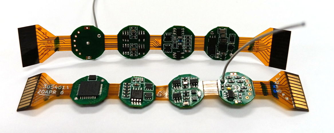
The A3054 is the first of our second-generation telemetry sensors, following the first-generation A3019, A3028, A3047, A3048, and A3049 Subcutaneous Transmitters (SCTs). See the Operation chapter below for a summary of the A3054 features and options. We have two fully-functional prototype ciruits built with all basic functions tested and working. All technical challenges have been met. We expect to have the first encapsulated prototypes ready for implantation in July 2026. See the Design page for the progress updates.
[04-JUN-26] We define the following part numbers for versions of the A3054 Intraperitoneal Transmitter (IPT). The part numbers all begin with "A3054".
| Version | Battery Capacity (μA·d) |
Volume (ml) |
Mass (g) |
Operating Life (dy) |
Shelf Life (mo) |
|---|---|---|---|---|---|
| A3054A | 3500 (2×SR936SW) | 1.7 | 3.2 | 35 | 12 |
The shelf life of the A3054 Intraperitoneal Transmitter is the time it takes to use up 10% of the battery capacity when the device is asleep on the shelf. The operating life is how long the device can produce reliable measurements when starting with a fresh battery. The operating life depends upon the telemetry protocol. In particular, it depends upon the total number of samples per second the telemetry protocol transmits. We calculate the operting life at 37°C using the following formula.
Where I_a is the active current, N is the number of active biopotentials, R is the total sample rate for all active telemetry channels, and I_xyz is the additional current consumed by thermometer and accelerometer measurement and transmission, should these be enabled. The A3054 uses one telemetry channels for each biopotential, acceleration, and temperature signal it transmits. The sample rates for the biopotential inputs will be any of 0, 64, 128, 256, 512, 1024 SPS, where 0 SPS means the input is disabled. The sample rate for temperature measurements will be 0 or 32 SPS. Even though the temperature measurement is being updated at only 1 Hz, we will transmit this measurement at 32 SPS on its own telemetry channel. The sample rate for accelerometer signals will be 0, 32, or 128 SPS. Even if we configure the accelerometer to provide an activity measurement with an update rate of 1 Hz, we will transmit this measurement at 32 SPS on its own telemetry channel. When we configure the accelerometer for 1-Hz update, I_xyz = 20 μA. When we configure it for three-axis acceleration measurement with update rate 100 Hz, I_xyz is 200 μA.
To illustrate the calculation of A3054 battery life, suppose we activate three iEEG inputs at 256 SPS. The A3054 will consume 40 + 9 + (0.092 * 768) = 120 μA. With a pair of SR936 batteries, it will run for 29 days. Or we could program the same device for 512 SPS on X1, 64 SPS on X2 and X3, plus 256 SPS on X4. The current consumption will be 134 μA. It will run for 26 days. If we configure X1-X4 for DC coupling, we can watch for ictal activity and spreading depolarization with one iEEG channel, spreading depolarization in two other iEEG channels, and measure both heart rate with the ECG input.
[29-JUN-26] The A3054 has four analog inputs: three uniploar and one bipolar. The unipolar inputs are designed for iEEG recordiung. The bipolar input is suitable for EMG, EEG, or ECG recording. We can enable or disable any combination of inputs. Any input that is disabled is not sampled and receives no telemetry channel. Any input that is enabled is sampled internally at 1024 SPS and transmitted externally on its own telemetry channel at one of the sample rates 64, 128, 256, 512, or 1024 SPS. The unipolar inputs are the X1 (red), X2 (orange), and X3 (pink). These share the same reference potential GND (blue), which we define to be 0 V, so we refer to the unipolar voltages as simply X1, X2, and X3. The biplar input is X4P (yellow) and X4N (green), and the voltage measured is X4 = X4P − X4N. The X1-X3 inputs can be configured collectively for AC or DC recording. When configured for DC recording, all three unipolar inputs are sensitive down to DC (0.0 Hz) and their dynamic range is ±56 mV. When configured for AC recording, they are sensitive down to 0.2 Hz with dynamic range ±15 mV. The bipolar X4 input is always DC-coupled with dynamic range ±45 mV.
The A3054 amplifiers provide gain with a low-pass filter function. The corner frequency of this low-pass filter is around 500 Hz for X1-X3 with DC-coupling, 130 Hz for X1-X3 with AC-coupling, and 400 Hz for X4. We see these corner frequencies in the figure entitled "Signal Amplitude versus Frequency, No Digital Filtering". The A3054 samples the low-pass filtered output from each amplifier at 1024 SPS. This sample rate is adequate to represent signals up to 512 Hz, but higher-frequency signals will suffer from aliasing distortion, whereby they appear in the digitized signal as signals of a lower frequency. The ideal low-pass filter would remove all signals above 512 SPS before sampling, but none of our filters are ideal. The 500-Hz low-pass filter of the DC-coupled X1-X3 amplifiers attenuates 1 kHz only by a factor of two compared to 10 Hz. The 130-Hz low-pass filter of the AC-coupled X1-X3 amplifiers provides sufficient attenuatiuon to eliminate aliasing distortion, but if we want to record signals in the range 200-500 Hz, this filter will attenuate their amplitude. The 400-Hz low-pass filter of X4 is somewhere in between.
The unipolar inputs, X1-X3, are designed to record iEEG, which is a signal with very little power above 200 Hz. We do not have to worry about aliasing distortion in iEEG when we are sampling at 1024 SPS. But we will have some amount of higher-frequency electrical noise generated within the A3054 circuit, and the 500-Hz and 130-Hz low-pass filters serve to reduce the amplitude of this electrical noise prior to sampling. The X4 input is designed for EMG, EGG, or ECG, and each of these signals can be recorded faithfully with the 400-Hz low-pass filter of the X4 amplifier. The EEG signal is chaotic with power all the way up to 600 Hz. But we don't want to record the shape of the EMG signal, we just want to measure its amplitude, and aliasing distortion does not change the signal amplitude. In the EGG signal, we will be using DC coupling, and the power above 400 Hz is far smaller than the slow-moving gut signals we are looking for, so aliasing will be insignificant. In ECG we have a signal with a fundamental harmonic in the range 5-20 Hz accompanied by harmonics all the way up to 200 Hz, but not much above that. The rest of the signal is chaotic and wide-band, so aliasing will not distort our pattern of ECG spikes. Thus we see that, despite the fact that the A3054 does not provide aggressive anti-aliasing filters, its high sample rate serves to render aliasing distortion insignificant for the signals it is designed to record.
After an A3054 Intraperitoneal Transmitter input has been samled at 1024 SPS, we can either transmit the raw samples on a telemetry channel, or we can accumulate samples and transmit an average sample value at a lower sample rate. We can, for example, accumulate sixteen samples and transmit the average of sixteen samples sixty-four times a second. This averaging of samples is called a "box filter". The A3054 can apply box filters of width 1, 2, 4, 8, or 16 samples to any of its inputs prior to transmission. Transmission costs ten times as much energy as sampling, so we extend battery life when we combine input samples and decrease the transmit sample rate. The box filters introduce their own low-pass filter function, which is overlayed upon that of the amplifiers. The figure entitled "Sweep Response for Various Sample Rates" shows the frequency response of the inputs for various transmit sample rates. The box filters provide a sharp initial drop in response above their corner frequency, followed by distinctive rebounds in response at higher frequencies.
When we record iEEG and ECG, the spectrum of the signal and the shape of its features are important to us. We detect seizures in iEEG, for example, by looking for coherent spikes, and we measure heart rate in ECG by finding the fundamental frequency of the ECG signal. For these signals, and for EGG as well, we want to filter out frequencies higher than half our sample rate so as to reduce aliasing distortion and preserve the shape of the voltage signal. Because the power of these signals drops dramatically with frequency above 10 Hz, attenuating higher frequencies with a filter does little to distort or attenuate the amplitude of the signal we want to record. The EMG signal, however, contains very little power below 10 Hz, and substantial power throughout the range 30-600 Hz. If we want to obtain a strong EMG signal, we should retain these higher frequency components. One option is to connect EMG to X4 and sample and transmit X4 at 1024 SPS. We will obtain a faithful and powerful recording of EMG. But we will also be consuming more power from our battery, which will reduce the operating life of our A3054 Intraperitoneal Transmitter. Most often, the only feature of the EMG signal that we are interested in is its amplitude. We might be making one amplitude measurement every eight seconds in order to determine in eigh-second intervals whether or not an animal is asleep. In order to measure the amplitude, we need only 64 SPS out of the available 1024 SPS, so we can configure X4 to transmit at 64 SPS with no box-filter and we will get an EMG signal that suffers from severe aliasing distortion, but nevertheless retains the correct amplitude. By transmitting at 64 SPS we reduce the transmission power consumption of the EMG signal by a factor of sixteen. For this reason, the X4 input of the A3054 can be configured to run with or without the digital box filter, regardless of the transmission sample rate.
[29-JUN-26] All members of the A3054 devices wake up and go to sleep with the application of a magnetic field. When A3054 is sleeping, its internal circuits are powered down. It will not respond to commands nor transmit any information. The only component on the board that is turned on is its magnetic sensor, which is waiting for a magnetic field to appear. While asleep, the A3054 consumes less than 1 μA. Even the A3054s with the smallest batteries can sleep for months and retain 90% of their battery capacity.
As soon as we wake up an A3054 Intraperitoneal Transmitter with a magnet, it flashes its lamp, which we hope will be visible through the epoxy encapsulation, loads its telemetry protocol from its non-volatile memory, calculates the current consumption of this protocol, and begins to execute the protocol. The telemetry protocol tells the A3054 which measurements to make and what signals to transmit. If we upload a protocol that disables all measurement, and transmission, the A3054 will be awake but inactive. We call this particular protocol the inactive protocol. When inactive, the A3054 consumes 40 μA at 37°C. It is ready to receive comands and can be updated with a new telemetry protocol using wireless commands. To transmit these commands, use the Telemetry Manager program and an A3042B-Series Telemetry Control Box (TCB). A mouse-sized A3054 with a 3500-μa·d battery capacity can remain inactive for three months before it exhausts its battery.
The telemetry protocol defines the measurements, sample rates, channel numbers, and bandwiths of the signals that the A3054 will digitize and transmit. Each A3054 has a unique factory-assigned four-digit hexadecimal code that cannot be altered once the A3054 has left our factory. When we transmit commands, we use this code to identify a particular A3054. All A3054s within range of the command transmitter will parse and examine every command, but only the A3054 with the specified ID will respond. There is, however, a wildcard ID, 0xFFFF, to which all A3054s respond. We can upload a new telemetry protocol to the non-volatile memory of any A3054 at any time with our command transmitter and the Telemetry Manager, which is included in our LWDAQ Software. Once the protocol is uploaded, we must re-boot the A3054 to implement it. We can re-boot the A3054 either with a wireless command issued by the Telemetry Manager or by turning the A3054 off and on with a magnet.
The A3054 provides three inputs that share the same reference potential. These are what we call the unipolar inputs, X1, X2, and X3. The unipolar inputs are designed for recording iEEG. Their reference potential, GND, is the ground potential of the sensor, so when we connect GND to the brain, we are grounding the sensor to the animal body. The unipolar inputs can be used with depth electrodes or surface electrodes. The amplifiers run off a 1.80-V power supply and use an internal 0.90-V power supply as their ground potential, so the potential of GND is actually 900 mV above the potential of the battery negative terminal. We can configure the three unipolar inputs for DC coupling or AC coupling, although we must pick either AC or DC for all three: we cannot configure them for AC and DC coupling individually. When configured with DC coupling, the amplifiers respond all the way down to 0.0 Hz. They can record spreading depolorizations. The amplifier gain with DC coupling is ×16, giving the amplifier input a ±900 mV / 16 = ±56-mV dynamic range. This range is adequate to accommodate the galvanic potentials generated by metal electrodes. When configured with AC coupling, the amplifiers introduce a high-pass filter with corner frequency 0.3 Hz. The amplifier gain with AC coupling is ×62, giving the amplifier a ±900 mV / 62 = ±15-mV dynamic range. The input impedance of the three unipolar inputs is 500 kΩ.
The A3054 provides one DC-coupled bipolar input consisting of two leads X4P and X4N. We implant these anywhere close together in the body to record a local biopotential. This biopotential is independent of the three unipolar potentials. The bipolar input amplifier subtracts the X4N from X4P to obtain the bipolar potential X4 and it amplifies X4 by ×20 to give us an input dynamic range of ±900 mV / 20 = ±45 mV. The differential impedance of the bipolar input is 200 kΩ.
We can enable and disable sampling of X1, X2, X3, and X4 separately. Whenever we enable an input, the A3054 samples the input at 1024 SPS. We call this the input sampling. The input sample rate is distinct from the transmit sample rate, which is the rate at which we transmit telemetry samples for the input signal. We can configure the transmit sample rate for each input independently. We select from transmit sample rates 64, 128, 256, 512, or 1024 SPS. If the transmit sample rate is less than the input sample rate, we can choose to accumulate samples, so as to transmit an average of the input samples that precede each transmit sample. This averaging of input samples is a type of digital low-pass filtering. For each channel, we either enable the digital low-pass filter or disable the filter. If we transmit X1 at 64 SPS and enable the digital filter, we will take the average of sixteen input samples to produce each transmit sample. For X1-X with digital filtering and DC-coupling the bandwidth of the transmitted signal is 25, 50, 100, 200, and 400 Hz for the five transmit sample rates. For X1-X3 with digital filtering and AC-coupling, the bandwidth of the transmitted signal are 25, 50, 100, 130, and 130 Hz. For X4, which is always DC-coupled, the digital filtering gives bandwidths 25, 50, 100, 200, and 400 Hz. Each active input must be assigned its own telemetry channel by its telemetry protocol. The channel numbers need not be consecutive, but we recommend that you make them consecutive so that analysis with programs such as the Event Classifier will be easier to arrange. Telemetry channel numbers lie in the range 1-254, subject to the restriction that their remainder after dividing by sixteen cannot be zero or fifteen. Thus 31 and 32 are not legal channel numbers.
The input impedance of the three unipolar inputs is 500 kΩ. At any time, the A3054 can, in response to a command, measure the impedance of its uniploar input electrodes in the following manner. It applies a −7.14-mV step to GND with respect to its own internal zero-volt potential. From the amplitude of the step we see in each unipolar input, we can deduce the resistance between the GND lead and the unipolar input lead. The precision of this measurement is roughly 0.5% of the unipolar input impedance, or 0.5% * 500 kΩ = 2.5 kΩ. The single bipolar input has its own reference potential and so should be unaffected by a shift in the unipolar ground potential. We cannot, therefore, measure the impedance of the bipolar electrodes.
The accelerometer can be configured in one of four ways. It can be disabled, it can provide an activity measurement updated at 1 Hz, or it can provide continuous acceleration measurements at updated at 25 Hz or 100 Hz. If updated at 25 Hz, the measurements will be tranmitted at 32 SPS, and if updated at 100 Hz it will be transmitted at 128 SPS. We can enable x, y, z or any combination of these. The x, y, and z accelerations each receive their own telemetry channel numbers and the accelerations are transmitted as unsigned, sixteen-bit integers for which 32768 cnt is the zero-value. The 1 Hz activity measurement is a sixteen-bit value that is the square root of the sum of the squares of the three acceleration components. The A3054 transmits this sixteen-bit value at 32 SPS even though it is updated only at 1 Hz.
The A3054's temperature sensor can be turned on or off. If on, it provides a sixteen-bit temperature measurement updated at 1 Hz with absolute accuracy ±0.05°C and resolution 0.0078125°C/cnt. The value 32768 cnt is 0°C. The temperature measurement will be transmitted on its own telemetry channel at 32 SPS.
The A3054 provides no measurement of battery voltage, but it does provide an estimate of remaining battery capacity. The A3054 estimates the current consumption of its telemetry protocol after reading the protocol from its non-volatile memory. It keeps track of how much of its nominal capacity it has used. It also keeps track of how many hours it has been operating for. Each time its battery consumption has increasd by another percentage point, it writes the number of hours for which it has been operating to its history. Even if we put the A3054 to sleep, the hour counter is retained. Every few seconds, A3054 transmits the percentage of battery capacity it has consumed. This transmission takes the form of an auxiliary message, and this message will be received and displayed by the Telemetry Manager, whether we are attending a live recording, or playing back an existing recording.
The A3054 provides a 512-Byte region of its non-volatile memory for user notes. These notes are recorded as ASCII text strings. The Telemetry Manager allows us to append text strings to the notes, or to over-write the existing notes with new notes. The notes allow us to record within each A3054 the details of its deployment in animals, such as the animal number, the times when experiments were performed, and its dates of implantation and explantation. We initialize the notes in the factory with notification of when the non-volatile memory was formatted, and when the battery was loaded.
During programming in our factory, we are able to format the A3054's non-volatile memory, set its unique four-digit hexadecimal identifier, calibrate its ring oscillator and radio-frequency transmitter, and initialize its run time and charge consumption counters. Once we remove the programming extensions from the circuit board, and encapsulate with a battery, these operations can no longer be performed. This inability to format and calibrate the device is a deliberate design feature. The A3054's operating code detects whether it is loaded with its programming extensions in our test fixture, and if so, it permits itself to be formatted and calibrated. Otherwise, it forbids access to all regions of its non-volatile memory other than the region that defines its telemetry protocol. Our intention is to make it impossible to cripple the A3054 with an accidental command, or to delete the device's history of battery use.
[04-FEB-26] For details of the design, development, and production of the A3054 Intraperitoneal Transmitter, see its Design page.