[27-JUN-25] Here we present the terminations and depth electrodes we can supply with our Subcutaneous Transmitters (SCT). An electrode is a component designed to acquire the electrical potential at some location in an animal's body. A lead termination is an electrically conducting component designed to connect to an electrode or to act itself as an electrode. The "D-Pin" termination is a gold-plated pin soldered to the end of an electrode lead, and it's express purpose is to mate with the "E-Socket" mounted of a depth electrode. But the "A-Coil" termination is 1 mm of bare steel helix at the end of an electrode lead, and it's express purpose is to be used as an electrode. We can deploy it as an EEG electrode by straightening, bending, cutting short, and fastening in place with a skull screw. Or we can deploy it as an EMG electrode by making a cut in a musle, inserting into the cut, being sure that the silicone insulation enters the cut, and securing the wire with cyanoacrylate. Whenever a termination mates with an electrode, the electrode is always a "depth electrode": one that penetrates into the brain, and by virtue of its mounting fixture and straight wire cannot be attached to the electrode lead before implantation, because we cannot tunnel the electrode under the skin to the skull during surgery without bending the depth electrode wire.
For a separate discussion of silicone-insulated electrode leads, see Flexible Wires. For instructions on soldering stainless steel wire and screws, see Solder Joints. For a discussion of the sources of the electroencephalogram (EEG), see The Source of EEG. For calculation and estimates of electrode impedance, see Electrode Impedance. For a presentation of the behavior of various electrode metals in response to DC signals, see Step Response of Metal Electrodes.
[27-JAN-25] Each lead of the a Subcutaneous Transmitter (SCT) or Implantable Stimulator (IST) has its own termination, and each type of termination has a name.
| Name | Description |
|---|---|
| A-Coil | Helix, 316SS, length 1 mm. |
| B-Screw | Screw, 0-80 thread, dia 1.6 mm, length 3.2 mm, slotted. |
| C-Screw | Screw, M0.5 thread, dia 0.5 mm, length 0.6 mm, flat. |
| D-Pin | Pin, dia 0.30 mm, length 2.1 mm, Mill-Max 4353-0-00-15-00-00-33-0, mates with E-Socket. |
| E-Socket | Socket, for pin dia 0.20-0.33 mm, Mill-Max 4428-0-43-15-04-14-10-0 |
| F-Pin | Pin, dia 0.64 mm, length 4.1 mm, Mill-Max 5035-0-00-15-00-00-33-0, mates with E363/0. |
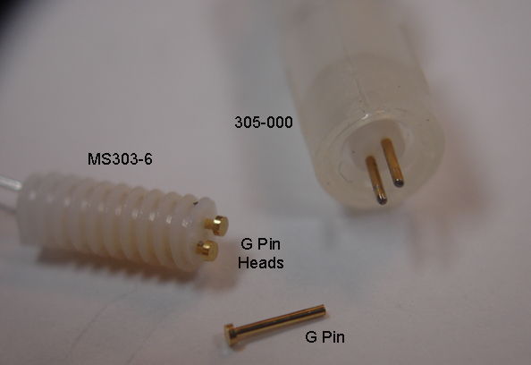
| G-Pin | Pin, dia 0.51 mm, length 4.4 mm, Mill-Max 5063-0-00-15-00-00-33-0, mates with MS303/6. |
| I-Pin | Pin, dia 0.30 mm, length 3.9 mm, Mill-Max 9083-0-00-15-00-00-38-0, mates with E-Socket. |
| K-Screw | Screw, 00-90 thread, dia 1.2 mm, length 1.6 mm, slotted. |
| L-Screw | Screw, 000-120 thread, dia 0.86 mm, length 1.6 mm, T1 Torx. |
| M-Wire | Solid wire, 125 μm dia Ag, insulation 250 μm silicone, length 15 mm. |
| N-Pin | Pin, dia 0.38 mm, length 3.2 mm, Mill-Max 4689-0-00-15-00-00-33-0. |
| P-Coil | Helix 316SS, length 3.0 mm. |
| Q-Ferrule | Crimp ferrule, length 2.0 mm, with 316SS helix, with inner dia 250 μm. |
A lead termination may itself be used as an electrode, or it might connect to a depth electrode during surgery. The A-Coil termination is almost always deployed as an electrode. But D-Pin always mates with an E-Socket on a depth electrode. The table below presents our depth electrodes.
| Name | Part Number | Description |
|---|---|---|
| H-Electrode | SDE-H | Depth electrode, wire 125-μm dia Pt-Ir, insulation 200-μm dia teflon. Locate with guide cannula, E-Socket mates with D-Pin termination. Obsolete. Guide cannula removed during surgery. Discontinued. |
| J-Electrode | SDE-J | Depth electrode, 125-μm dia 316SS wire, insulation 200-μm dia teflon. Locate with guide cannula, E-Socket mates with D-Pin termination. Guide cannula removed during surgery. |
| R-Electrode | SDE-R | Depth electrode, straight wire 125-μm dia 316SS, insulation 200-μm dia teflon. Locate with guide cannula, E-Socket mates with D-Pin termination. Guide cannula remains in place after surgery. |
| W-Electrode | SDE-W | Depth electrode, straight wire 125-μm dia 316SS, insulation 200-μm dia teflon. Locate with hypodermic tube, E-Socket mates with D-Pin termination. |
| X-Electrode | SDE-X | Depth electrode, wire 125-μm dia 316SS, insulation 200-μm dia teflon. Locate with hypodermic tube, crimp wire into Q-Ferrule. |
| Y-Electrode | SDE-Y | Depth electrode, wire 75-μm dia 316SS, insulation 140-μm dia teflon. Locate with hypodermic tube, crimp wire into Q-Ferrule. |
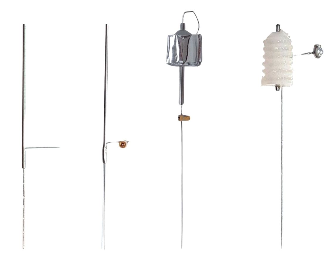
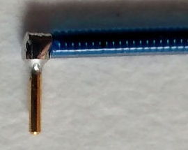
By default, we solder screws, pins, and sockets perpendicular to leads and wires. But if we precede the electrode letter code with a lower-case "s", the pin, screw, or socket is parallel to the lead or wire, as shown below.
Some lead terminations can act as electrodes themselves. The screws we can push into a skull hole. The bare helix we can straighten and bend to fit in a skull hole.
Whatever we attach to the ends of the SCT leads must be small enough to be drawn up under the skin of the neck to the head. If we want to use a depth electrode with an SCT, we connect the depth electrode to the lead during surgery using a pin and socket contact or a crimp contact. Order depth electrodes at the same time as your transmitters, and we will try to make sure your transmitter leads have matching terminations. The pin and socket connection is slightly easier to perform than the crimp contact, but the crimp contact generates less noise.
See SCT Implantation for an introduction to the implantation procedure. See Coiled Wires for video demonstration of stripping silicone from the ends of our electrode leads. See the Solder Joints chapter of our Flexible Wires page for instructions on tinning bare stainless steel wire in preparation for soldering to your own screws and pins.
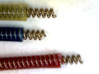
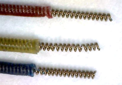
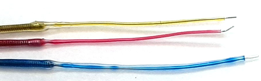
[17-JUN-25] Of all our electrodes, the A-Coil is the most popular. Our electrode leads contain a stainless steel, helical spring that acts as its conductor. The wire itself is 316SS. For details about the leads themselves, see the Leads chapter of our Flexible Wires page. To make an A-Coil termination we remove 1 mm of the silicone at the end of the lead, revealing the spring helix itself. A P-Coil is 3-mm of bare spring metal.
By far the most common use of the A-Coil is to create an angled wire for insertion into a skull hole. We stretch out the helix and bend the straightened wire at right angles.
The A-Coil can be re-created at the end of a freshly-cut lead with the help of a scalpel. When we re-use an implant, the simplest procedure is to cut off the ends of the leads to free them from the cement used to hold them in place in the first implantation. We create a new A-Coil by removing insulation from the cut lead. When you order an SCT, you specify the insulated length of the leads. Add 5 mm for each time you want to be able to cut the leads back and re-implant your telemetry device. We use a scalpel to remove silicone from the tip of the lead so as to expose the bare wire. Consult the Insulation Removal chapter of our Flexible Wires page for detailed instrutions and tutorial videos showing how to remove insulation from our 0.5-mm and 0.7-mm leads.
Electrodes that are free of solder, such as the bare wire secured with a steel screw, generate less low-frequency chemical artifact than electrodes that contain an exposed solder joint.
For instructions on how to use the A-Coil to record electrocorticography (ECoG) and electromyography (EMG), and electrogastrogram (EGG), see the Implantation chapter of the Telemetry Manual.
[10-APR-24] We make straight, silicone-insulated, solid-wire electrode by soldering a solid wire into the spring before we coat with silicone. In order to hold a reliable coat of silicone, the wire must be at least 125 μm in diameter. Our M-Wire is 125 μm bare silver wire we have soldered into a spring and insulated.
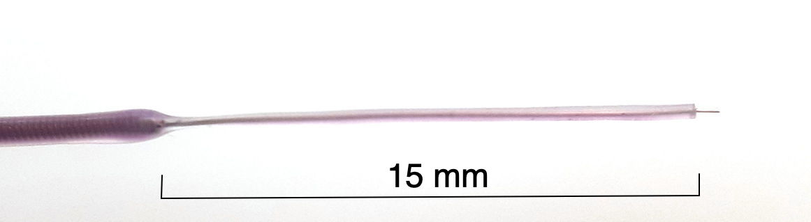
We can use the tip of the M-Wire as an electrode of diameter 125 μm, or we can remove some of the silicone insulation to make a longer electrode. We remove silicone from the end by cutting around the wire with a sharp scalpel and a gentle hand, then removing the detatched silicone segment.
There is little point in attaching a solid stainless steel wire to the end of one of our electrode leads. The steel wire inside the lead is perfectly adequate whenever we want a stainless steel contact. Platinum or platinum-iridium might be useful as a solid wire, but we have not yet been asked to make them.
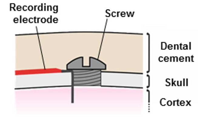
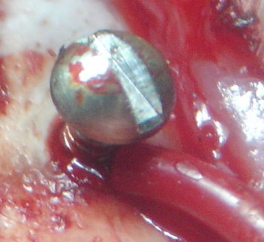
[20-FEB-24] Stainless steel screws are useful as electrodes for electroencephalogram (EEG) and electrocorticogram (ECoG) because they are easy to anchor to the skull. We drill a hole slightly smaller than the screw and thread the screw into the hole. There are two ways to connect our electrode leads to screws. One is to solder the lead to the head of the screw. The other is to use the screw to hold the end of the lead in the skull hole. Solder joints can simplify surgery, but they to generate chemical artifact. When we solder a lead to the screw, the electrode is the tip of the screw, and our recording is EEG. When we feed a wire through the hole, we can make the wire long enough to penetrate the brain, and keep the screw short enough so that it does not protrude beneath the skull. Our recording will be ECoG. Once our lead and screw are in place, we will fix the screw to the skull hole with cyanoacrylate. We cover with dental cement. The dental cement insulates the screws from body fluids and nearby muscles.
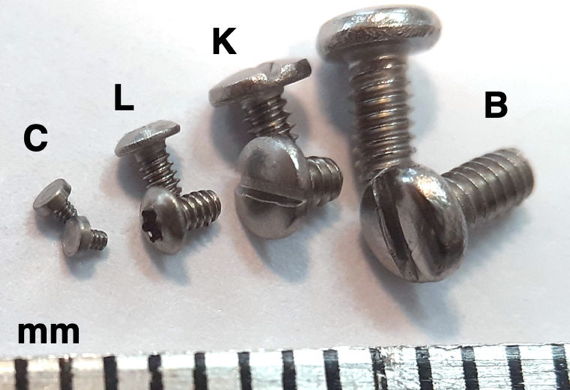
We stock four sizes of screw for implantation. We assign each a letter code for use when ordering transmitters. The table below gives the dimensions of each type, and provides a link to a drawing.
| Drawing | Type | Diameter (mm) | Pitch (mm) | Length (mm) | Head (mm) | Applications |
|---|---|---|---|---|---|---|
| B-Screw | 0-80 1/8" | 1.52 | 0.32 | 3.2 | Slotted | Rat skull when >8 weeks. |
| K-Screw | 00-90 1/16" | 1.2 | 0.28 | 1.6 | Slotted | Rat skull when <8 weeks. |
| L-Screw | 000-120 1/16" | 0.86 | 0.21 | 1.6 | Torx T1 | Rat or mouse skull electrode. |
| C-Screw | M0.5-0.125-0.6 | 0.50 | 0.125 | 0.6 | Flat | Mouse skull electrode. |
When we solder a lead to a screw, we solder the tip of the lead to the head of the screw. If the screw is large enough, we can keep the joint to one side of the slot in the screw, allowing the surgeon to turn the screw with a screwdriver. During surgery, we have a pick-up lead connected to the screw, so the lead rotates along with the screw. In order to make sure the pick-up lead relaxed and untwisted when the screw is in its final orientation, we must pre-twist the screw by the number of turns required to thread it into its hole. We are able to solder the lead to one side of the slot only for our B and K-Screws. For the smaller L and C-Screws, we fill the top of the screw with solder. These screws are so small that there is no need to thread them into a skull hole. We simply press them in.
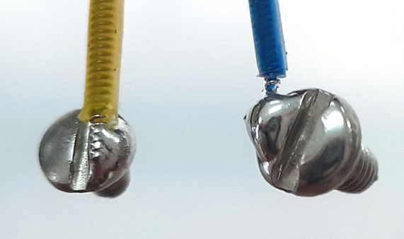
When we fasten a wire into a hole with a screw, we have no solder joint. The head of the screw is always free of solder, so we can instert a screwdriver into the head. But the C-Screw has no slot for a screwdriver, so we must always press it into place. The L-Screw provides a socket for a Torx T1 bit, which is not a standard piece of laboratory equipment. We will provide a Torx T1 bit with your first order of L-Screws. The K and B-Screws have slotted heads.
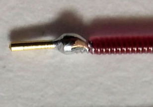
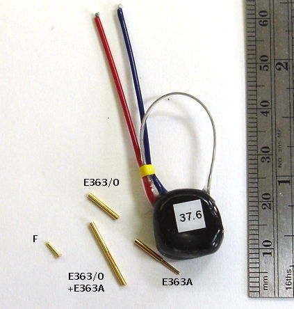
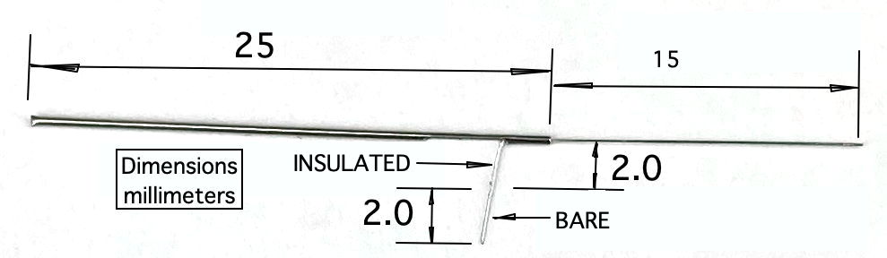
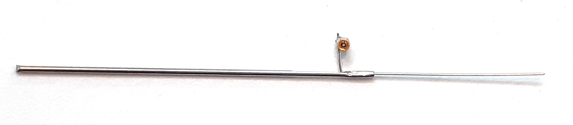
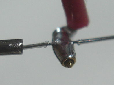
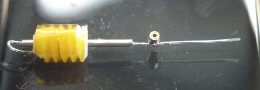
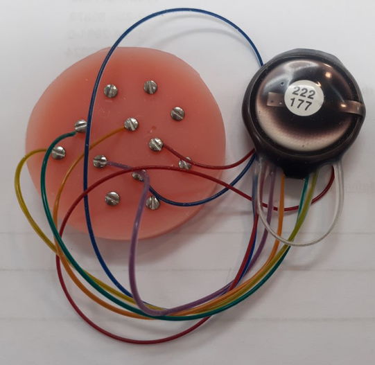
[05-FEB-16] Gold-plated pins allow us to connect the end of our EEG lead to depth electrodes. The depth electrode is too cumbersome to pass easily beneath the skin of an animal from the transmitter to the head. The pin, on the other hand, is easy to move up under the skin. Our contact pins are made by Mill-Max, and are summarized in their data sheet. The photograph below shows our D Electrode, which mates with our H and J Electrodes.
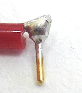
The pins are easy to solder to a steel wire. They provide a gold-plated finish, which mates well with the gold-plated finish of a socket, to provide a corrosion-resistant electrical contact within dental cement saturated with water vapor.
Our F and G eletrodes are pins that mate with electrodes made by Plastics One. When you choose an electrode with a socket, we will look at the socket drawing and choose a pin that will fit sungly and take up as little vertical height as possible, to keep your implantation compact.
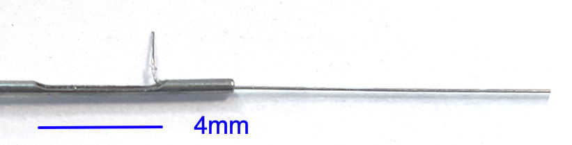
[12-FEB-24] A crimp contact is one where we bring together two wires we want to join, surround them with a steel tube, squeeze the tube, and so hold the two wires together. We call the steel tube the crimp ferrule. No solder is involved. We eliminate the chemical artifact that is generated by the galvanic potential between solder and steel. Crimp contacts are reliable when at least one of the two conductors acts as a compression spring. In our crimp contacts, the helical electrode lead acts as the compression sring, pushing outwards on the ferrule and the straight, solid wire provided by a depth electrode. We insert the stright wire into the core of the helix, slide the ferrule over the helix, and squash the ferrule with pliers.
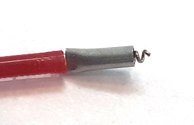
We combine the helix with the ferrule so as to simplify the crimping process, creating the Q-Ferrule. We slide the 2-mm ferrule onto a 3-mm P-Coil. We squeeze the ferrule at the base of the P-Coil so as to hold it in place. We trim the end of the P-Coil so that only half a millimeter of helix protrudes. When it comes to making the crimp contact, we slid the 2-mm bare end of a 125-μm diameter stainless steel wire into the helix. We push it in as far as it will go. We squeeze with pliers to complete the contact.
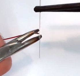
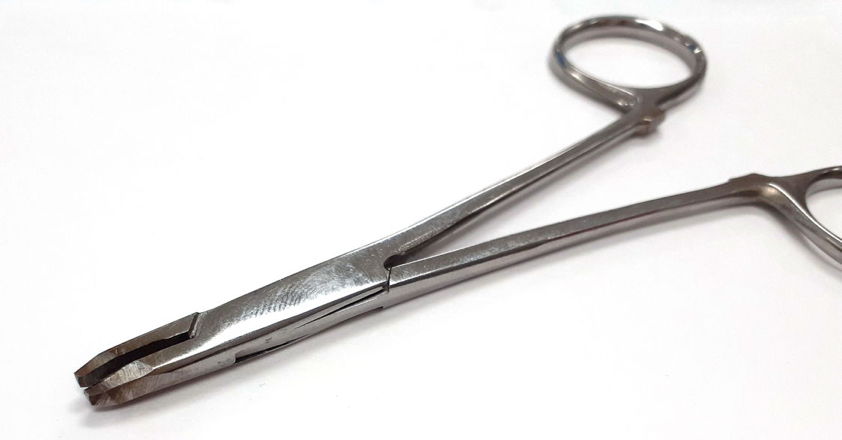
The crimp contact requires that the bare steel wire enter the central cavity of the helical lead. The spring in our B-Leads has outer diameter 450 μm and inner diameter 250 μ. A bare 125-μm diameter steel wire fits easily into the helix of the spring. The ferrule is 2-mm long with inner diameter 510 μm and 50-μm walls. The ferrule squashes the helix and wire together, creating a press-contact that is maintained despite movement and stress by the compression of the spring. To perform the crimp, we recommend modified forceps, like the ones shown below. We cut off the forcep clamps, cut short the forcep jaws, and grind the jaws down until they are 2 mm wide at the tip, and 4 mm high. During surgery, we hold the Q-Ferrule in the jaws of these pliers, and slide it over the bare steel wire to which we want to make a crimp contact, and squeeze as tightly as we can to squash the ferrule.
When you want to make a crimp contact, specify the Q-Ferrule with the letter "Q" in your part sensor part number's electrode list. When re-using an SCT, remove insulation from the end of the lead with the help of a scalpel, as shown in this video.
[20-JAN-20] We have three gauges of hypodermic 304SS tube: 304H23XX (20 mil inner diameter, 2 mil wall, Gauge 23XX), 304H22XX (22 mil inner diameter, 3 mil wall, Gauge 22XX), and 304H21XX (29 mil inner diameter, 2 mil wall, Gauge 21XX). We cut 3-mm sections of each by scribing with a triangular file until we break through the wall, then breaking by bending with pliers. Run a 0.4-mm diameter steel probe through the interior to round the ends. The result is 3-mm crimp ferrules. The 23XX is barely larger than our 18-mil helical lead. We screw the helix through the ferrule, put our 5-mil diameter stainless steel wire inside from the other end, and crimp. The 22XX is wide enough for the helix to slide through easily, but we can crimp the helix in place by squeezing one end of the ferrule. The 21XX is fragile, but with care we make the ferrules. When compressed, they are wider, but they work just as well. We would prefer 316SS for our ferrules, but 316SS tubes with 2-mil wall thickness are not available in 20-mil diameter. Our previous ferrules were 304SS, and we like the ease with which the thin-walled tube can be crimped. We order from MicroGroup 1000 of 2-mm ferrules made with the 304H23XX.
[05-APR-23] Our crimp contacts have become easier to use and easier to make over the years. We began by wrapping the straight 125-μm diameter solid wire of the X-Electrode in a 3-mm length of 450-μm steel helix. We demonstrate crimping a 250-μm helix to a 125-μm wire with this original procedure in this tutorial video. Later, we eliminated the extra piece of helix and crimped the wire and lead together immediately with a laser-cut ferrule, as we show in this tutorial video. Our current solution is to partially-crimp one end of the ferrule to the lead helix, so that we can grab the ferrule and lead with forceps, slide onto the electrode wire, and crimp with one hand.
[23-JUN-25] To reach farther into brain, we need a stiff, insulated wire. The wire will come supplied longer than you need. You cut the wire back to the length you require. You can square-cut the end, or you can cut it at an angle so that it has a bevel to better penetrate the brain. When implanting with a subcutaneous transmitter (SCT), we run the SCT lead along the surface of the skull to the electrode and attach the lead to the electrode either with a crimp contact or a socket contact. During surgery, the depth electrode must be held firmly while we make this contact. Afterwards the electrode must be maneuvered into the correct location on the skull and lowered to the correct depth.
Each electrode provides a mounting fixture by which we can hold the electrode during surgery. In the case of the X and W-Electrodes, the mounting fixture is a laser-cut steel tube, which we call our Depth Tube. In the case of the R and J-Electrodes, the mounting fixture is a threaded plastic pedestal. Within the pedestal is a steel cannula guide. To secure an electrode to the skull, we place an anchor screw through the skull nearby and enclose the depth electrode and the anchor screw with cement. Depending upon the type of electrode, we either remove the mounting fixture and seal with another layer of cement, or we leave the mounting fixture intact to act as a cannula guide.
The standard X-Electrode, part number SDE-X, has wire length 15±1 mm, allowing the user to cut it back to the length they want. If you know your desired length ahead of time, we can cut the wire to a length as short as 1.5 mm with accuracy ±0.2 mm. The electrode with wire length "x.y" millimeters has part number SDE-X-XMY. Part number SDE-X-1M6, for example, is an X-Electrode with wire length 1.6±0.2 mm.
The X-Electrode provides a 450-μm diameter stainless steel tube as a mounting fixture. To hold the tube, we recommand a clamp like the RWD 68201, which attaches to your stereotactic mount. The tube has a slot cut into it, out of which we run the electrode wire for connection to an electrode lead with a crimp contact. Because the crimp contact does not contain any solder, the signal recorded by the electrode will contain far less low-frequency chemical artifacts. Crimp contacts allow us to record slow signals like cortical spreading depressions (CSDs). For use with the crimp contact, we must use one of our B-Leads with a crimp ferrule on the end, which we call a "Q-Ferrule". The video below shows how to crimp the X-Electrode to a bare helical wire.
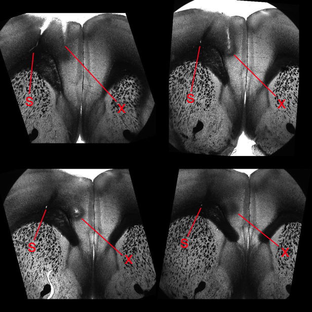
Any wire we bury in body tissue will cause damage and scarring. For an example of damage caused by an implanted X-Electrode and neighboring injections, see these brain slices, which show damage to the brain of a mouse caused by injection and recording.
The Y-Electrode, part number SDE-Y, is similar to the X-Electrode, but is equipped with a thinner wire, which in theory will cause less trauma to brain tissue. The Y-Electrode wire is 140-μm teflon insulation around a 75-μm solid 316SS wire. For details see photograph and drawing. The standard Y-Electrode, part number SDE-Y, has wire length 5±0.5 mm, allowing the user to cut it back to the length they want, but we can cut the wire to lengths as short as 1.5 mm with accuracy ±0.2 mm. Part number SDE-Y-XMY has wire length "x.y" millimeters.
The R, W, J, and H-Electrodes all provide a socket into which we can plug a gold-plated pin. The pin that fits the socket is the D-Pin termination that we can provide at the end of any subcutaneous lead. The W-Electrode, part number SDE-W, is an X-Electrode equipped with a socket. The W-Electrode introduces two solder joints into the electrode: one between a helical lead and the pin, and the other between the electrode wire and the socket. Do not use W-Electrodes to record cortical spreading depressions. The W-Electrode is easier to implant than the X-Electrode because sliding a pin into a socket is easier than crimping a ferrule onto a bare wire.
Our drawing of the W-Electrode is identical to that of our X-Electrode, except that the bare wire of the X-Electrode has a socket soldered to it. The standard SDE-W part has wire length 15±1 mm, but the SDE-W-XMY part has wire length "x.y" millimeters as short as 1.5 mm and with accuracy ±0.2 mm.
The R-Electrode, part number SDE-R, provides a cannula through which we can inject a substance into subject animal's brain, and an adjacent electrode wire through which we can record local field potental. The standard SDE-R part has wire length 10±1 mm. The SDE-R-XMY has wire length "x.y" millimeters within the range 1.5 mm to 15 mm. We cut the shortest wires with accuracy ±0.2 mm. The R-Electrode guide cannula provides a threaded pedestal onto which we screw a dummy cannula to seal the guide tube when it is not in use. We ship every R-Electrode with a dummy cannula. To deploy an R-Electrode, we use a stereotactic clamp that grabs the pedestal.
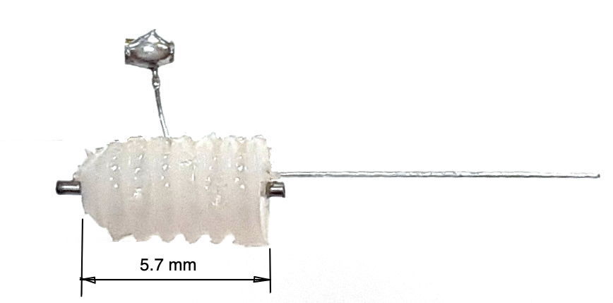
The R-Electrode wire is parallel to the cannula tube and emerges 150±150 μm from the guide tube at the base of the pedestal. The pedestal itself is 5.7 mm long. The cannula guide is the a modified C315GS-5SP from Protech International. We modify the pedestal by grinding down the guide tube until it protrudes only 0.5 mm beneath the pedestal. The cannula tube is stainless steel, 26-gauge, inner diameter 250 μm, outer diameter 470 μm. The dummy cannula we ship with the R-Electrode is the C315DCS-5/SPC from P1Technologies.
The J-Electrode, part number SDE-J, provides a straight stainless-steel wire mounted to a within a steel cannula guide. We connect our electrode lead to the J-Electrode by means of a socket soldered to the wire. The wire is insulated below the socket, but it is bare above the socket. The cannula guide is a C313GS-5/SP from Protech International. The guide cannula pedestal is a threaded plastic pice 5.7 mm long. The guide cannula itself is a steel tube cut 5.0 mm below the pedestal. The tube is stainless steel, 22-gauge, inner diameter 390 μm, outer diameter 710 μm.
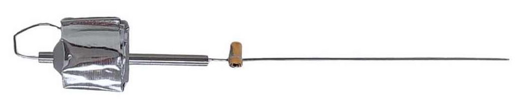
To deploy a J-Electrode, we need a stereotactic clamp that grabs the pedestal. Once the J-Electrode is in position, we cover the socket with cement, but we take care not to bury the tip of the cannula tube. We cut the bare steel wire where it emerges from the top of the cannula pedestal and raise the cannula off the wire. We cut the wire off where it emerges from the existing cement, and cover the exposed wire tip with more cement. The advantage of the J-Electrode over the X and W-Electrodes is the ease with which we can cut the J-Electrode wire and remove the guide.
The standard J-Electrode, part number SDE-J, has wire length 10±1 mm, where the wire length includes the diameter of the socket. The SDE-J-XMY has wire length "x.y" millimeters, within the range 3 mm to 15 mm. We cut the shortest wires with accuracy ±0.3 mm. Our collaborators at ION/UCL provide a pictoral implantation protocol, and in the steps below, we provide a written implantation protocol.
| Step | Description |
|---|---|
| 1 | Examine electrode and locate the opening on the socket. |
| 2 | Press transmitter lead pin into the socket to confirm they fit together. |
| 3 | Remove D-Pin from socket. Do not bend the electrode wire. |
| 4 | Cut electrode wire to length. |
| 5 | Sterlize with alcohol. |
| 7 | Mount guide cannula in stereotactic clamp. |
| 8 | Implant transmitter and insert lead pin into socket. |
| 9 | Lower wire into skull hole until socket rests upon skull. |
| 10 | Coat skull around socket with VetBond or equivalent cyanoacrylate. |
| 11 | Cover socket with dental cement, staying clear of the cannula tube. |
| 12 | Wait for dental cement to cure, cut wire loop at top of guide cannula. |
| 13 | Raise clamp to pull guide cannula off the wire. |
| 14 | Cut the wire flush with the top of the dental cement. |
| 15 | Cover the wire stub with dental cement. |
The H-Electrode is obsolete. It provided a platinum-iridium wire, but was otherwise identical to the J-Electrode. Now that we have a reliable source of straightened, full-hardened stainless steel wire, we no longer make electrodes with platinum-iridium wire. The stainless steel is much stiffer, and when it comes to depth electrodes, stiffer is better.
[26-SEP-15] Edinburgh University implants the prototype H-Electrode in transgenic mice. The figure below shows depth and surface field potentials recorded simultaneously with a dual-channel subcutaneous transmitter. The surface and reference electrodes are 0.5-mm screws.
When implanting the H-Electrode, the Edinburgh group monitored EEG from the H-Electrode while lowering the tip of the electrode into the hippocampus. They adjusted the depth of the electrode until they obtained the largest possible EEG amplitude. The 125-μm tip of the depth electrode has impedance roughly 10 kΩ, compared to 2 kΩ for the screw. The depth recording has baseline amplitude 400 μV compared to 80 μV for the surface recording. There we see one or two step artifacts per hour in these dual-channel recordings. But the artifacts are shared between the depth and surface recordings, like this, so they cannot be the result of movement of the H-Electrode alone.
[08-AUG-16] We receive archive M1470389836.ndf from ION/UCL. Two A3028H-DDC transmitters are implanted in two conscious, freely-moving mice with two J-Electrodes each. Amplitude is roughly 80 μV from all channels. We look through the hour-long recording and see none of the step artifacts that motivated the development of the H and J-Electrodes.
We note that ION/UCL did not adjust the depth of the J-Electrode to obtain the maximum amplitude of EEG, but rather set the depth to a certain value during implantation without monitoring EEG.
[05-FEB-16] Conductive epoxy might allow us to cement a bare wire directly onto the skull in two places so as to provide EEG recording without drilling any holes. We tried silver epoxy, as we describe below. The recordings pick up muscular activity from the scalp of the host rat, which we see also in un-insulated screw electrodes. Such activity we can detect and classify in order to distinguish it from EEG. The recordings showed continuous drift in the baseline voltage, not by transient steps as we see in poorly-secured wire electrodes, but as a drift of several millivolts over one-second intervals. Such drifts we can overcome with our event classification. The conductive epoxy recordings are, we believe, adequate for event detection. But the electrodes themselves are not as reliable as screws, in that they tend to come loose. More work with silver epoxy might increase reliability, but such work has not yet occurred.
[12-AUG-10] CHB implanted transmitter No10 and glued the ends of the analog wires to the animal's skull using silver epoxy, which provides an electrically conducting contact. With these contacts, we observed seizure-like activity in a non-epileptic rat, as shown here in archive M1281121460. We are convinced that the epoxy contacts are picking up EEG. Later, in archive M1281455686, we can compare No10's contacts with No8's steel screw contacts. When we say baseline signal we mean the signal low-pass filtered to 1 Hz or so, which is a measure of the average value of the signal over a fraction of a second.
From this one experiment, we see the baseline swinging up and down compared to the stable baseline we obtain from the screws. But the silver epoxy contact sensitivity compares well to that of the bare wires, and exceeds that of the screw contacts.
The following plot shows power in the 2−20 Hz band for the two transmitters during three hours of recording.
The peak power from No10 corresponds to vigorous seizures like this one, not any transient spikes or level shifts. In addition to seizure detection, the silver epoxy contacts are also sensitive to wave bursts in the 40−160 Hz band. The plot below shows simultaneous wave-bursts from No8 (screws) and No10 (epoxy).
It appears that the silver epoxy has only one disadvantage compared to screws: a moving baseline. But the moving baseline does not appear to interfere with seizure or wave burst detection, and the silver epoxy method does not require holes in the skull.
[30-MAY-17] The movement of electrodes with respect to the surrounding animal tissue will add step-changes in potential to the EEG signal. By default, we equip the amplifiers in our SCTs with a high-pass filter with cut-off frequency 0.3 Hz. When a step-change passes through this high-pass filter, it come out looking like a pulse with a sharp front edge, followed by a relaxation half a second long. The theoretical step response of the A3028B, for example, is the blue graph shown here. If we solder the two leads of a transmitter together, drop the transmitter in water, and stir it around, the standard deviation of the signal is less than 20 μV and we see no step artifact. If we separate the leads and allow them to measure the variation in electric potential in the water as we stir, we see 1-mV rumble, but not sharp steps. When we allow the electrodes to make intermittent contact with one another as we stir that we start to see 10-mV steps in the signal. We call these steps "movement artifact". The longer-term changes in potential that we observe with amplifiers that have no high-pass filter we call "chemical artifact", and we discuss those artifacts separately.
Movement artifact arises in EEG recordings when the electrodes are not secured with respect to the skull. As implanters have learned to secure wires and screws more effectively to the animal skull, the frequency of these artifacts has decreased. In mice, these artifacts are particularly difficult to eliminate. Here are some examples of movement artifact from mouse recordings.
Here we see pulses caused by steps of order 10 mV, which are shaped into pulses by the transmitter's high-pass filter. In the figure below we see far larger artifact from the same M0.5 skull screws in another mouse.
Here we see large artifact with more complex progression, also from skull screws in a mouse. The amplitude is 15 mVpp.
We are not certain of the origin of the following features. The two traces are from a dual-channel transmitter implanted in a mouse. If the electrode potential of the common electrode changes, we expect the effect upon the X and Y channels to be shared. If the electrode potential of either X or Y changes, we expect to see the effect only on X or Y. Here we see opposite changes in X and Y.
The number of movement artifacts in a recording varies greatly from one implant to the next, and is a strong function of who performs the surgery. Recordings from rats tend to have fewer than one artifact per hour for all experienced implanters. Movement artifact in mice varies from fewer than one per hour to hundreds of artifacts per hour. Those implanters whose recordings are almost free of artifact have reduced the artifact rate by working on better anchoring of their electrodes on the mouse skull. We are currently working on developing a guide to successful implantation in mice.
[24-JUN-25] Our standard SCTs and HMTs are AC transmitters. They provide a 0.2-Hz high-pass filter to remove steady-state galvanic potentials generated by the electrodes, and also to attenuate slow changes in these galvanic potentials. If we want to look for phenomena such as cortical spreading depolarizations (CSDs), or slow changes in electrogastrogram (EGG), we must use a DC transmitter. The passband of our DC transmitters extends all the way down to zero Hertz (0.0 Hz). Any SCT or HMT with a "Z" in its part number is a DC transmitter. To convert an AC transmitter into a DC transmitter, we remove the high-pass filter and reduce the gain of the amplifier. Once we extend the passband down to 0.0 Hz, we must concern ourselves with changes in galvanic electrode potential. These changes take place over tens of seconds, or they can be semi-permanent and of order tens of millivolts. We decrease the gain of DC transmitters so as to increase their input dynamic range, which ensures that we can accommodate these changing galvanic potentials. When a galvanic potential varies over a period of tens of seconds, we call the variation a chemical artifacts. Solder joints combined with stainless steel will generate a sustained galvanic potential when immersed in saline, and variations in this galvanic potential appear in our recordings as chemical artifact. No matter how hard we try to keep water off a solder joint in a head fixture, it makes its way to the solder joints and generates chemical artifact. Here is an example of chemical artifact recorded from a mouse with depth electrodes that use soldered pins and sockets.
To reduce chemical artifact, we eliminate solder joints. One way to eliminate solder is to use a crimp contact between our lead and depth electrode. Another way is to hold a bare steel wire in place on the skull with a screw. The crimp contact provides better immunity to movement.
[18-JAN-19] We would like to compare the number of chemical artifacts generated by crimp and screw contacts. Both these contacts are free of solder, but the crimp contact is secured by a squashed steel ferrule pressing on a spring, while the screw contact is secured by a thread pressing a wire into a rigid mounting material such as bone or, in our experiment, dental cement. We take two transmitters with bandwidth 0-160 Hz and place them in 1% saline in two separate petri dishes, as shown below.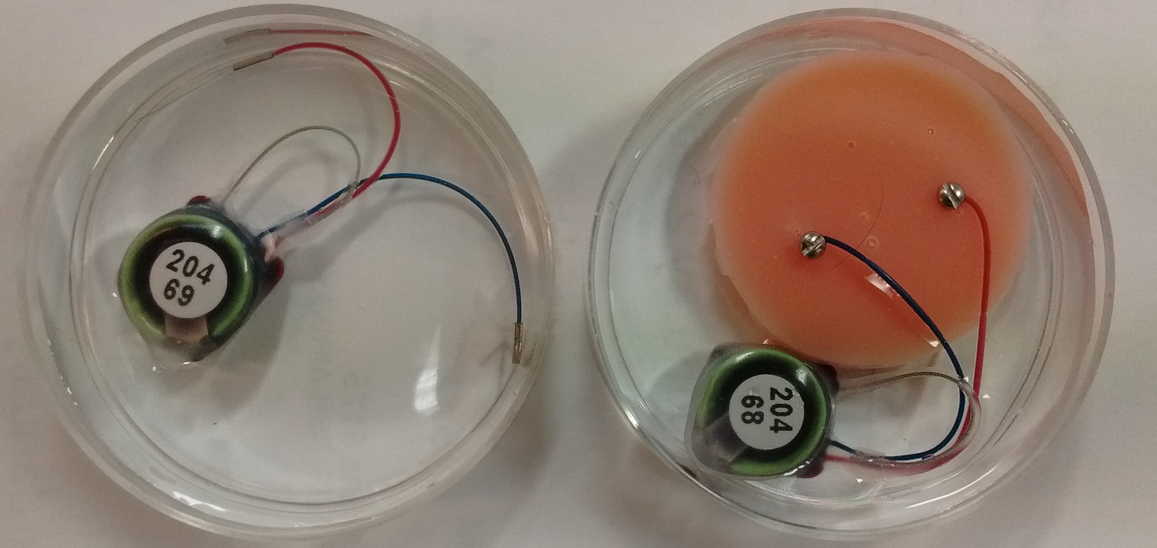
One device we equip with two crimps, one leading nowhere and one connecting to a bare steel wire. The other device we equip with two screws and a mock animal skull made out of dental cement. We record continuously for two days within a faraday enclosure that is disturbed only be changes in ventilation and lighting.
During the night, when the lights are off in the OSI office, nobody is moving around, and nobody is touching the table upon which our experiment is running, the recordings are like the example shown below.
During the day, we see step changes in potential followed by relaxation on both channels. We call these "pulse artifacts". In forty-eight hours of recording we see 31 pulse artifacts from the screw electrodes and 9 from the crimp electrodes. The recording below shows several pulses from the screws.
We sometimes see changes in both signals occuring at the same time. In M1547588237 we see a pulse from the crimps occurring at the same time as a linear decrease in the voltage recorded by the screws. The screws suffer from more pulses, but the crimps show more short-term drift, as in M1547599037, and occasionaly larger drift as in M1547602637. When we return to the petri dishes after two days, the electrodes are still covered with water, but barely so. We perform a series of tests.
After this hour, we leave the dishes alone. The salt is dissolving. The lights and heating are on. For the next three hours, we see only one pulse. Raw data M1547825546. Other than this pulse, the signal remains stable to ±100 μV.
[12-FEB-24] We record for ten days from this arrangement of screws in dental cement, immersed in stationary 1% saline. Two of the signals recorded by the A3047A1B-A transmitter extend to 0.0 Hz, so we use these to look for chemical artifact.
The downward spike at time 6.5 days occurs only in the Y-input, see here, which suggests it is generated by a chemical reaction at either the Y+ or Y− electrodes, not by movement, light, or temperature, which would affect all electrodes.
[09-MAY-19] Our collaborators at ION/UCL implanted an A3028SZ2-AA equipped with two X-Electrodes crimped to the bare ends of the leads. There are no solder joints. The frequency response of this device is 0.0-80 Hz with dynamic range ±100 mV. The plot below shows the first fifteen hours of recording after implantation, overlayed upon one another.
The drift of several millivolts in the first two hours is consistent with the transmitter battery voltage settling after it is first turned on. In the subsequent 26 hours we find no sign of chemical artifact. The animal dies an hour before the end of the recording, and after death, we see the potential rise by 5 mV in 20 minutes.
[01-MAR-21] Crimp contacts used with a recording bandwidth of 0.0-160 Hz record cortical spreading depression (CSD), as shown below.
Here is an example of a spontaneous seizure recorded with 0.0-160 Hz showing changes in EEG baseline during a spontaneous seizure.
For crimp contacts, we must select our B-Type leads, which provide a 450-μm steel helix that is well-suited for crimping to electrode wires.
[02-JAN-25] For a chronological account of our development of our electrode catalog, see our separate Development and Production page.