[11-JUN-24] The Direct Fiber Positioning System (DFPS) Auxiliary Circuits are those that support and control the actuators, as well as those that provide guide sensor on the fiducial plate. The Backplane (A3044BP) consists of a long, rigid circuit board into which we plug multiple service boards, such as the Base and Service Board (A3043). The Fiducial Plate (A3044FP) holds guide sensors and fiducial fibers around the tips of the DFPS masts. The Cell Support (A3044CS) holds the DFPS cells, to which we attach it with soldered pins.
The backplane provides connectors for service boards, as well as connectors that deliver ±250 V to the system for electrode drive, 2.4 V and 1.2 V for logic and conversion, and SDO and SDI for communication with the fiber controllers.
The cell supports hold the actuator cells by means of soldered pins. The fiducial plate provides guide sensors and fiducial fibers in the same plane as the tips of the masts.
We installed the A3044BP-A in our DFPS-TS2 (DFPS Test Stand Two). The A3044BP-B, A3044CS-A, and A3044FP-A are designed for the DFPS-80A, an eighty-positioner instrument that we can populate with anywhere from one to five cells of actuators.
The Power Supply (A3044PS) converts LWDAQ ±15 V into ±250 V and presents the high-voltage output on a shrouded four-way header.
The following versions of the DFPS Backplane (A3044) are defined.
| Version | Connected Boards | Geometry | Comment |
|---|---|---|---|
| A3044BP-A1 | 3 × A3043A | 80 mm × 17.5 mm for 3 × 20-mm Cells | Backplane for DFPS-TS2. |
| A3044BP-B1 | 3 × A3043B | 120 × 18 mm for 3 × 20-mm Cells | Backplane for DFPS-80A. |
| A3044FP-A1 | 2 × A2086A | 100 mm × 100 mm for 5 × 20-mm Cells | Fiducial Plate for DFPS-80A. |
| A3044CS-A1 | 3 × A3043B | 120 mm × 19 mm for 3 × 20-mm Cells | Cell Support for DFPS-80A. |
| A3044PS-A1 | 1200 × A3045A-1 | 85 mm × 60 mm | Power Supply for DFPS-80A. |
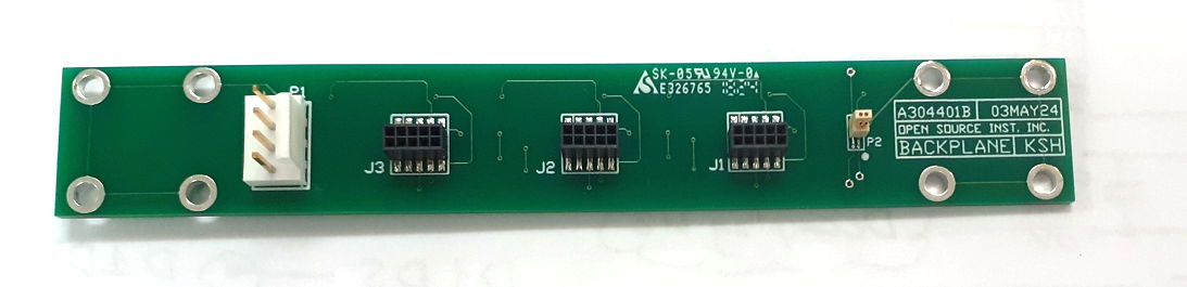
[24-MAY-24] The DFPS Backplane (A3044BP) provides connectors for three DFPS cells. Separate regulators provide 2.40 V and 1.20 V for the fiber positioners of each cell. A shared +5V power supply enters through a four-way connector on one end of the backplane, along with Serial Data In (SDI). A shared Serial Data Out (SDO) line leaves the backplane through the same connector. A larger four-way connector on the other end of the backplane brings ±250 V to the cells.
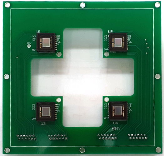
S3044BP-A_1: Schematic of TS2 Backplane (A3044BP-A).The DFPS Fiducial Plate (A3044FP-A) provides four ICX424AL image sensors that we can read out through four vertical through-hole FLEX-12 sockets, and four non-plated through holes for 2.5-mm ferrules holding fiducial fibers.
S3044FP-A_1: Schematic of DFPS-80A Fiducial Plate (A3044FP-A).The DFPS Cell Support (A3044CS) provides support for positioner cells. The A304403A holds up to A3043B base boards in place with four pins each. Rectangular apertures allow optical fibers to pass out the bottom of the base boards out of the positioner array.
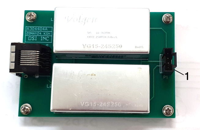
A304403A.zip: PCB for DFPS-80A Cell Support.The DFPS Power Supply (A3044PS) provides ±250-V power for the positioner actuators. Input is a LWDAQ cable, which provides ±15 V. Output is a shrouded MOLEX-4 that provides ±250 V and two 0-V contacts. The power supply can deliver up to 60 mA, which is adequate for 1200 fiber controllers.
A304404A.zip: PCB for DFPS-80A Actuator Power Supply.[11-JUN-24] The A304401A had the following problems, all of which we corrected in the A304401B.
[18-JUL-22] We have the bridge plate mounted on our Test Stand Two, ready for the backplane. The Direct Fiber Positioning System (DFPS) Backplane (A3044BP) consists of a long, rigid circuit board into which we plug multiple service boards, such as the DFPS Base and Service Board (A3043).
[13-OCT-22] Backplane connections and power supplies designed, schematic S3044A_1. Printed circuit board outline and connector locations fixed. We will be using 50-mil pitch two-row, ten-way headers and sockets to hold the service boards to the underside of the backplane. Regulators will provide 2.4 V and 1.2 V to the service boards, one set of regulators per service board. For the logic power supply and communication we are going to try out the PZN hermaphroditic connectors from Omnetics, a four-way surface-mount vertical connector on the underside of the backplane. We will glue it in place and see how well it lasts. We will use a mating part with wires soldered to its pins. These wires will run to a Command Transmitter (A3029C), which will provide command transmission through SDI to the fiber controllers on the service boards, as well as 3.3V or 5V power for the backplane regulators. We use the TPS70912DBV to provide 1.2 V at up to 150 mA, which is enough to blow the 50 mA fuse on a fiber controller if there should be a fiber controller short of 1V2. We use TPS7A2024 to provide 2.4 V for 2V5. The logic power supply VL on the backplane can be anything from 3.0 V to 6.0 V.
[17-OCT-22] Ordering A304401A PCB for backplane.
[20-DEC-22] Assemble our first A3044BP-A. Loading P2 we note pad rows too close together, but we are still able to make joints. In loading the connector we choose the orientation for future assemblies. We have PZN-04-WD-18, the same connector with 18-inch leads. If we rotate the connector we end up with black for +5V and red for 0V, which goes so against traditional color assignments that we prefer the mixed-up colors of below.
|
|
[21-DEC-22] We connect 5V power and SDI to our A3044BP-A using our PZN-04-WD-18 cable harness. We see 2.4 V on 2V5 and 1.2 V on 1V2. We connect a base and service board A3043A and into the service board we in turn plug a fiber controller A3045A. The fiber controller is running fine. We have tested all connections except the high voltage. The fiber controller receives and responds to serial commands received through P2.
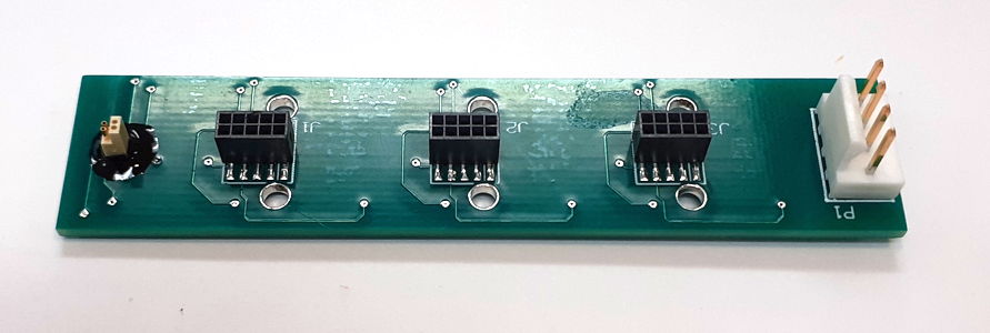
[30-DEC-22] We rip P2 off the board: solder joints break. Apply black DP270 epoxy to hold it in place.
[29-APR-24] The A304402A is the PCB for the Fiducial Plate (A3044FP) of the DFPS-80A.
The A3044FP provides four ICX424AL guide sensors, each of which we read out with its own flex cable. It provides four fiducial fibers in 2.5-mm zirconia ferrules. The cross-cut in the center allows for a full compliment of 5 * 16 = 80 fiber positioners, but we will be loading only the center four for our DFPS-4A. The PCB is designed to mount onto a square block that we can rotate for calibration.
[01-MAY-24] We complete the A304403A PCB for the DFPS-80A Cell Support (A3044CP-A). The PCB provides eight mounting holes for use with brackets. The brackets are spaced 100 mm for compatibility with a 25-mm grid M6 base plate.
The A304401B is the PCB for the DFPS-80A Backplane (A3044BP-B). It provides the same circuit as the A304401A, but with dimensions and mounting holes matching those of the A304403A. We correct the assignment of pin numbers to the PZN-04-VV connector so our numbers match the Omnetics data sheet. We move the logic and power connectors out of the way of the mounting brackets, still keeping them on the same side of the circuit board as the service connectors, out of the way of the fibers that will be running along the top side.
| A3044 Color | P2 Pin | S3044C Name | A3029F Color | A3029F Name |
|---|---|---|---|---|
| Black | 1 | SDI | White/Blue | X1 |
| Brown | 2 | 0V | Brown | 0V |
| Red | 3 | SDO | Blue | X2 |
| Orange | 4 | +5V | White/Brown | 5V |
This board uses the same mounting holes as the Cell Support. It will be mounted behind the cell support with the same brackets. The top side of the board faces the cell support. The brackets go on the top side, but must not interfere with the pins of P1, nor any vias near P2.
[24-MAY-24] We have the A304402A Fiducial Plate PCB, A304401B Backplane PCB, and the A304403A Cell Support Plate in hand. We have the A304301B Base and Service Boards as well. They all fit together. We are ordering the A304404A Power Supply PCB today.
[11-JUN-24] Assembled first A3044PS-A power supply board, no errors.
[13-JUL-24] We prepare a cable harness to connect our A3044PS-A to our A3044BB-B. We have pin 1 green 0V, pin 2 yellow +250V, pin 3 white 0V, pin 4 blue −250V. We have re-assigned the pins on the PZN-04-VV connector on the backplane. We now have pin 1 brown SDI, pin 2 black 0V, pin 3 orange SDO, pin 4 red +5V. We move the wires on both of our A3029F controllers. Connect controller to service board to backplane to power supply and command transmitter. Move mast tip in a square, working fine.