page-chunkmatch-prompts-onlyHow do I secure an Electrode Interface Fixture (EIF) to the head of a mouse or a rat? What is the procedure for mounting a Head-Mounting Transmitter (HMT) on the head of a mouse or a rat? Can you show me photographs of the surgical protocol for EIFs? How do I replace an HMT?
Acknowledgement: Photographs and instructions provided by Neela Krushna Codadu, PhD, and Kate Hills, PhD, Postdoctoral Research Fellows at UCL. The method for securing EMG electrodes to muscle tissue was described to us by Joel Raymond, PhD, Postdoctoral Research Fellow, Rutgers University.
Disclaimer: Surgical and animal welfare requirements vary across institutions. Consult your institution's veterinary staff to ensure compliance with local guidelines.
Warning: Unwrapped HMTs are vulnerable to static electricity. Do not transport unwrapped HMTs while wearing rubber shoes, wool sweaters, or any other static-generating item of clothing.
Disclaimer: The method we describe for securing EMG electrodes has not yet been validated by our customers.
Introduction
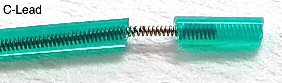
[06-MAR-26] This protocol describes how to attach an Electrode Interface Fixture (EIF) to the skull of a mouse or rat, and how to attach a Head-Mounting Transmitter (HMT) to the fixture after surgery. Each EIF comes equipped with a number of leads that are to act as electrodes. In this protocol we assume all leads are silicone-insulated, color-coded spring leads. The blue lead is the ground potential and is always present on every EIF. It must be always be grounded to the cerabellum with a brain surface electrode, regardless of what other signals you want to record. The other leads will be a combination of intracranial electroencephalogram (iEEG) and electromyogram (EMG) electrodes. By "iEEG" we mean either electrocorticogram (ECoG) or local field potential (LFP), which is what our brain surface and brain depth electrodes detect respectively. If an EIF is equipped with depth electrodes, they will already be attached to the ends of their respective leads. The other leads will be terminated with a length of bare steel coil. The length of this coil will be 1 mm for a bare wire electrode and 3 mm for a soft tissue electrode. We will use bare wire electrodes as our brain surface electrodes, and we will use a soft tissue electrodes as our EMG electrodes. We will try to make it clear when a procedure or item of equipment is needed only for iEEG recording, and when it is required only for EMG recording.
The colors of the leads on our latest Electrode Interface Fixtures (EIFs) do not match the colors shown in the photographs of this protocol, although they do match the colors in the diagrams.
Ensure the EIF and its electrodes are assembled and intact.
Ensure muscle electrode leads have 3 mm of exposed steel coil at the end.
Ensure brain surface electrodes have 1 mm of exposed steel coil at the end.
If you need to expose more wire, follow the instructions in Insulation Removal.
Confirm that the EMG wire coils will fit into your syringe needle.
Prepare ECoG surface electrode leads. These have 1 mm of bare steel coil at the end. Hold the lead insulation near the tip with one pair of tweezers. Grab the end of the bare coil with another pair of tweezers. Stretch the coil until it is mostly straight. Make a right-angle bend in the wire 1 mm from the insulation. Trim the end of the lead so its length equals the skull thickness plus your desired cortical depth.
Sterilize all surgical tools prior to use.
Calibrate and check stereotactic apparatus.
Animal Preparation
Weigh the animal and record its weight.
Anesthetize the animal according to your institutional guidelines.
Perform toe-pinch to ensure proper anesthesia depth.
Administer pain medications according to your institutional guidelines.
Place the animal on a heating pad or temperature-controlled surgical platform.
Place the animal in a stereotactic stand, connect to anesthetic, and apply eye lubricant.
Disinfect the surgical site.
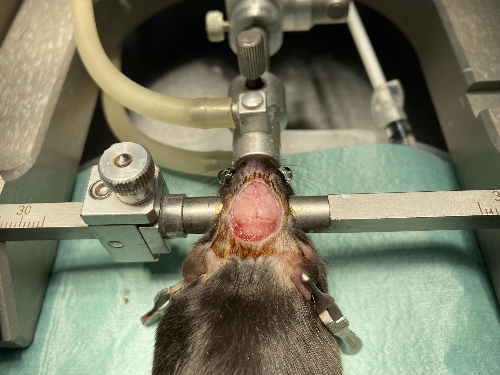
Head Incision
Figure: Head Incision and Scalp Exposure.
Use forceps and scissors to lift the scalp and remove a patch of skin. Expose the top of the skull. This is where you will mount the EIF and implant the iEEG electrodes.
Extend the existing incision a few millimeters beyond the skull to expose the trapezius muscles on the neck. Expose both trapezius muscles. You will be implanting one electrode in each.
Apply cyanoacrylate to the skin edges to prevent bleeding and to secure the skin in place.
Do not allow cyanoacrylate to touch the animal's eyes.
Do not allow cyanoacrylate to touch the animal's skull, we want to clean the skull first.
Skull Cleaning
Clean the skull surface of connective tissue using a bone scraper.
Apply hydrogen peroxide to the skull and immediately dry with cotton swab.
Remove any remaining connective tissue on the skull with bone scraper.
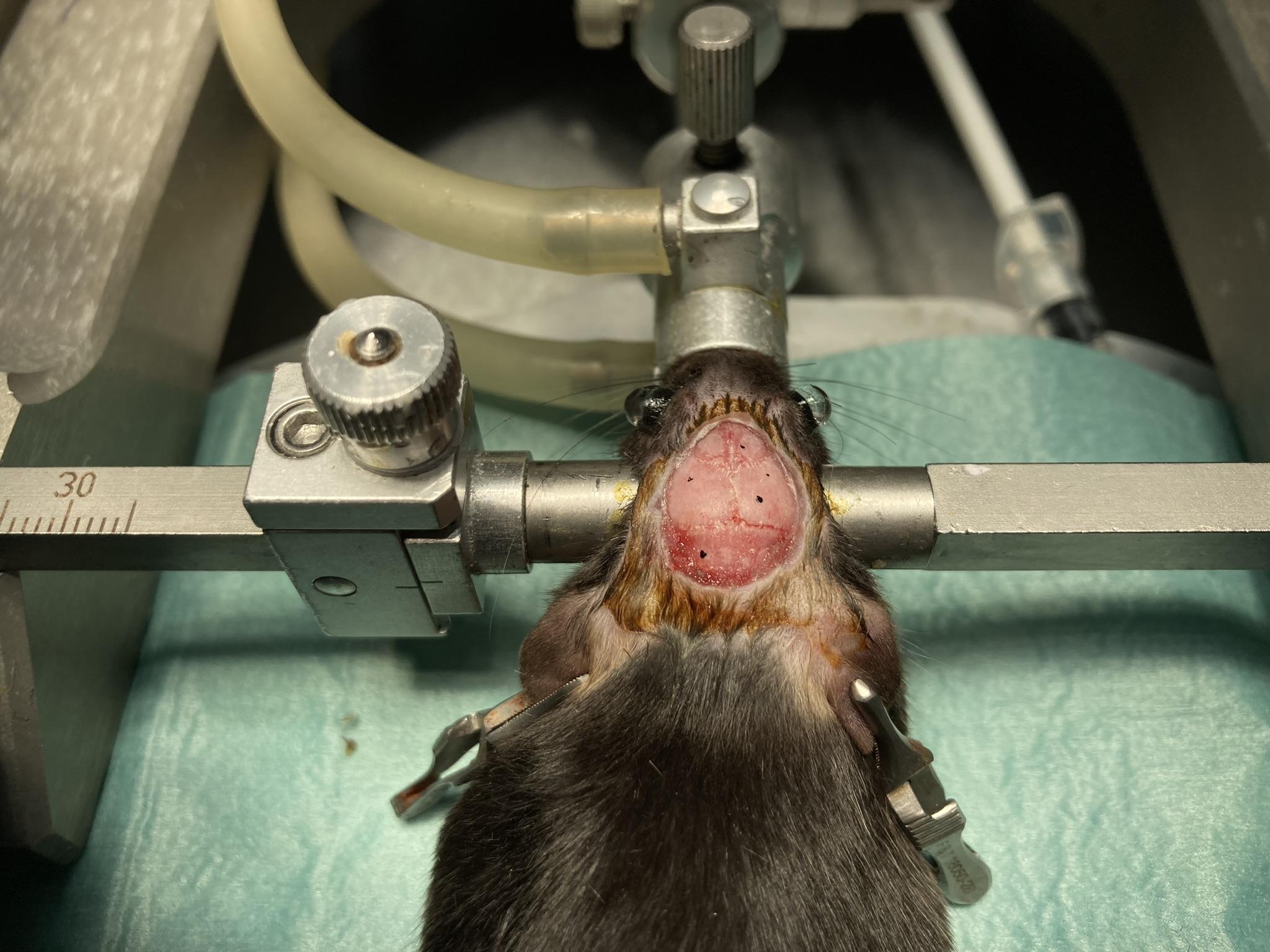
Burr Hole Drilling
Figure: Burr Hole Mapping.
Glue the skin of the scalp in place with Vetbond to prevent bleeding and keep skin retracted for surgery.
Zero the stereotactic stand using the bregma as your reference.
Using your stereotactic apparatus, locate the desired burr hole coordinates, and mark them on the skull with your sterilized marker.
Drill burr holes at marked positions. Drill down until a thin layer of bone remains to cover the dura. Use a sterile syringe needle or sharp-pointed tweezers to poke through the remaining bone to the dura.
If you are going to anchor bare-wire electrode in these holes, confirm the screws fit in the burr holes.
Dab excess fluid with sterile cotton.
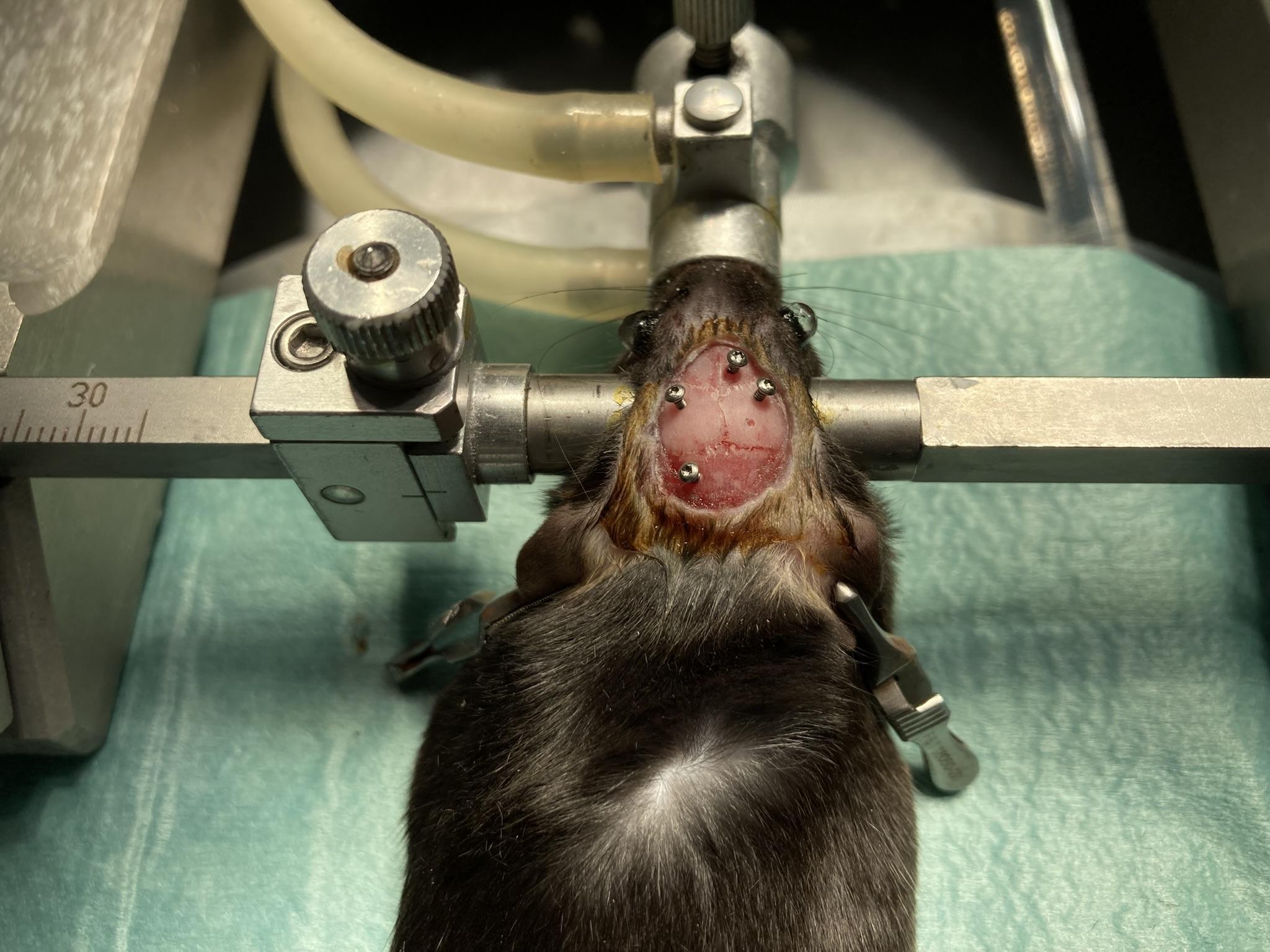
Figure: Testing the Fit of the Fastening Screws.
EIF Placement
When you place the EIF for the first time, and before you fasten it to the skull, you have an opportunity to see if the electrode leads are the correct length. Each lead must make its way to its recording site, but excess lead will eventually have to be bundled up and then buried in dental cement. Our silicone spring leads are not easy to bundle. Our annealed stainless steel wires are far more easy to bundle, but they are harder to work with and to not stretch if they are too short. It is our sincere hope that your leads are already cut to the correct length when you get to this stage of the surgery, and that all the lead ends are prepared and ready for implantaion. If you you must trim the leads, mark them with a sterile marker, remove the EIF from the mount, and cut them with iris scissors. You can remove insulation from the end of silicone-insulated spring leads by following these instructions. Once you are satisfied, remount the EIF and lower into position on the skull.
Figure: An EIF Lowered to Just Above the Scalp. We will measure and mark the required lead lengths.
Secure the EIF in the stereotactic arm.
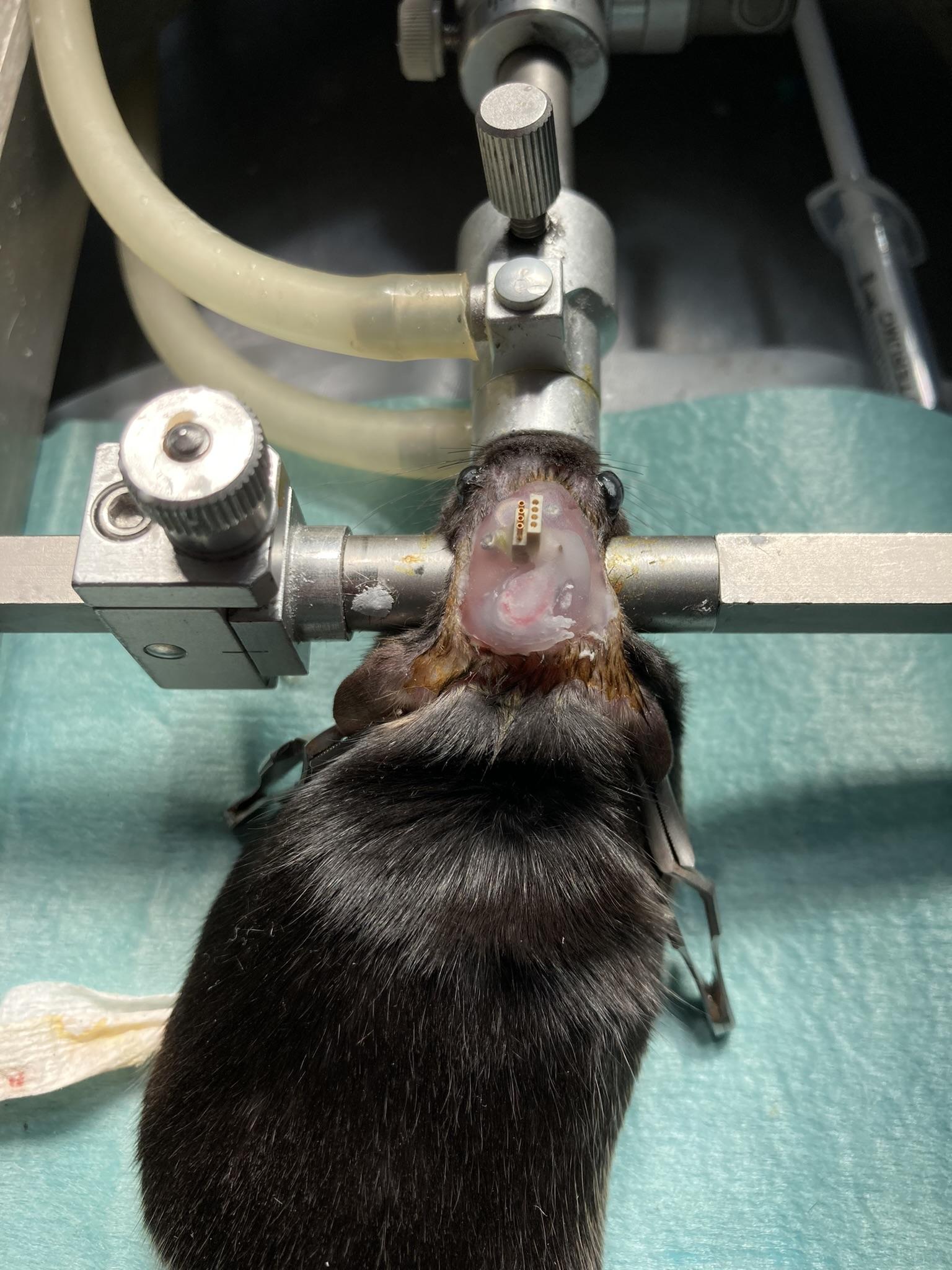
Align the EIF with the anterior-posterior axis. The exposed gold-plated tubes of the connector should be on the left, as seen looking from the animal's posterior.
This orientation of the EIF is mandatory because the HMT antenna must protrude over the animal's back, not its nose.
Lower the EIF so that the epoxy on its base just touches the skull.
Make sure there are no wrapped underneath the EIF.
Apply a small amount of dental cement around the underside of the EIF.
Do not allow the detal cement to flow into your burr holes.
Waith a couple of minutes for the dental cement to cure.
Notes:
Electrode interface fixtures (EIFs) are not reusable once they have been implanted.
Head-Mounting Transmitters (HMTs) are reusable until they are chewed upon by an animal.
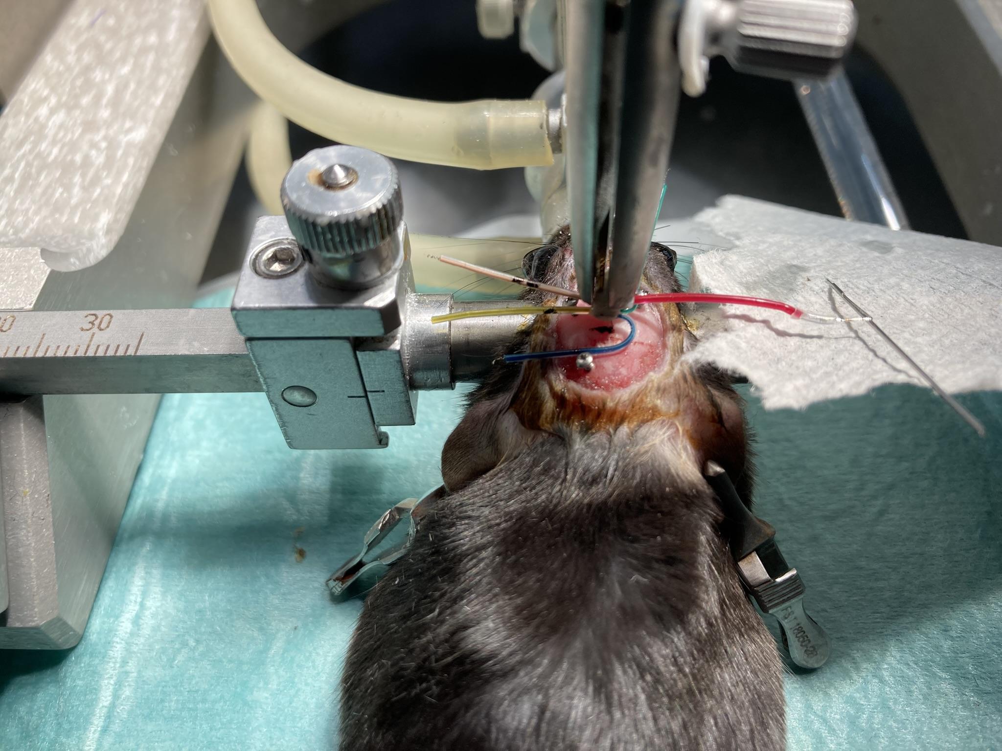
iEEG Implantation
We consider two types of iEEG electrode: brain surface electrodes for ECoG and brain depth electrodes for LFP. Implant the surface electrodes first, then lower the depth electrodes with the clamp of your stereotactic mount.
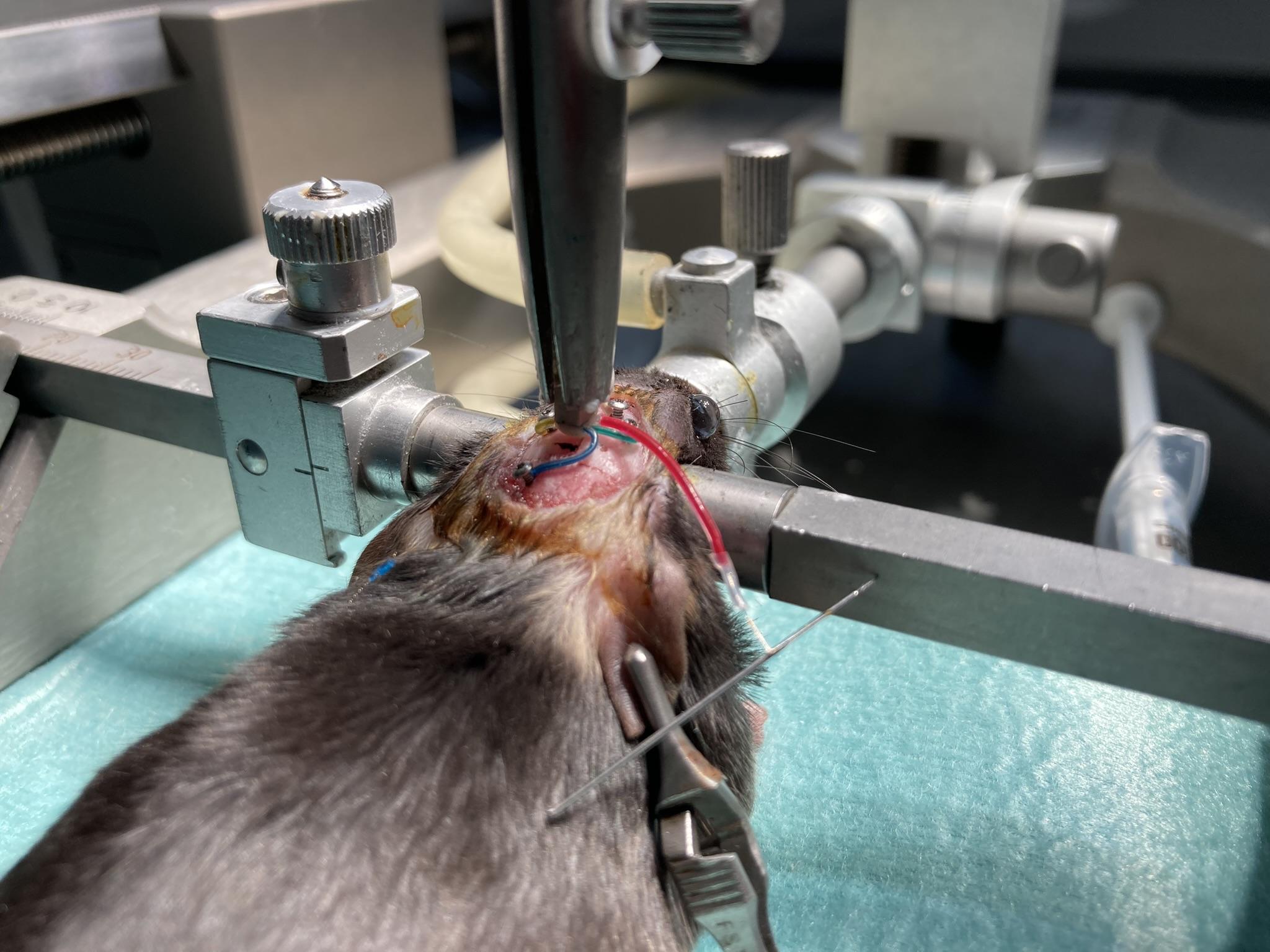
Figure: Surface Electrodes and Accompanying Set Screws Implanted. A depth electrode dangles to the side by a red lead, waiting to be implanted.
We begin with the surface electrodes, of which there will always be at least one: the blue lead is the ground that we must implant over the cerabellum. The tips of these leads have already been prepared in Step 2.
Test screw fit in burr holes; holes should be slightly smaller for a snug fit.
Insert the surface electrode into the burr hole, securing it with tweezers.
Leave a short section of exposed wire on the skull before the bend, so as to stop the screw from catching on the lead insulation.
Secure a portion of the lead insluation to the skull with a little cyanoacrylate. Make sure you do not allow cyanoacrylate to seep into the burr hole.
Having secured the lead, you should now be able to release it and pick up the screw and screwdriver.
Insert the screw into the burr hole and turn. If the electrode wire binds to the screw, release the screw and instead hold the electrode lead before you turn the screw further.
If bleeding occurs, dab with a cotton-tipped applicator.
Apply cyanoacrylate around the burrholes to prepare them for dental cement.
Make sure no cyanoacrylate penetrates the burr hole. Cyanoacrylate can form an insulating layer over the electrode wire tip, attenuating your ECoG signal.
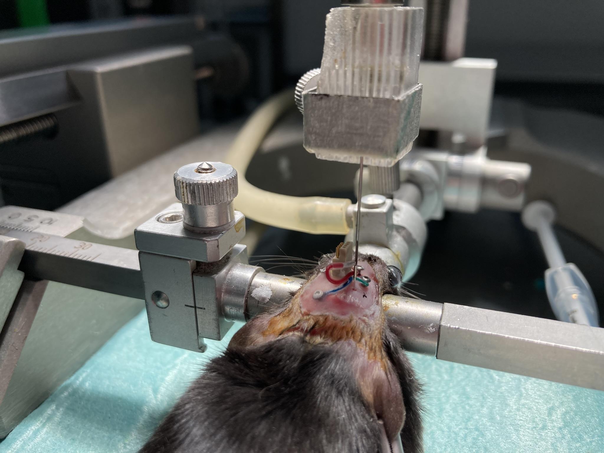
With the surface electrodes in place, we are now free to position our depth electrodes. Consult our Electrode Surgery Protocol for instructions particular to each type of depth electrode.
Clamp the depth electrode in the stereotactic mount.
Lower into place.
Apply cyanoacrylate to the skull around the burr hole.
Apply dental cement to the depth electrode where it emerges from the skull.
Each type of depth electrode has its own unfastening or clipping procedure. Perform these now.
Wrap excess leads around the EIF to reduce protrusion.
Cover the leads, depth electrodes, and skull screws with a first layer of dental cement to secure them in place.
Figure: All iEEG Electrodes Implanted and Secured With Screws. We coat screws with vetbond to prepare them for bonding to dental cement.
EMG Implantation
To record EMG, we use a soft tissue electrode made out of an S-Coil termination. This termination will be applied to the end of one of the 0.5-mm leads provided by the Electrode Interface Fixture (EIF). The S-Coil provides exposed steel coil to pick up the EMG signal within the chosen muscle as well as an insulating silicone tip to make sure that we do not record the potential outside the muscle. If we allow our electrode to make electrical contact with the fluid outside the muscle, we will see a strong ECG signal in our EMG, and detection of activity will be difficult. If we are imlanting an electrode interface fixture to record EMG, we are most likely going to place the two electrodes in the trapezius muscles. One option is to place both in the same muscle, another is to place them in opposite muscles. In the diagrams below, we illustrate the procedure where we implant in opposite muscles. We begin by implanting the end of the purple EMG lead in the left trapezius muscle.
Figure: Insertion of EMG Leads Into the Neck of a Mouse or Rat. We use a syringe needle to create a passage through a trapezius muscle. We insert the S-Coil at the end of our EMG lead into the needle.
Identify the top of the two trapezius muscles and locate the midline between them.
There will be two EMG leads. In our diagram they are green and purple.
Insert the needle on the side of the neck opposite the natural location of the electrode lead.
The needle should create both an entrance into and an exit from the muscle.
The tunnel should be roughly 2 mm long and penetrate 1 mm into the tissue at its deepest point.
Control bleeding with sterile cotton and leave the needle in place.
With the needle still in the muscle, insert the S-Coil at the end of the purple EMG lead into the needle tip.
Having placed our soft tissue electrode for EMG recording in the left trapezius muscle, we now secure it with a suture and insulate the end of the electrode with a cap.
Figure: Securing EMG Leads to the Neck of a Mouse or Rat. Suture each lead in place and cover the exposed end with a wire cap.
Remove the needle while holding the wire in position with tweezers.
Once you have removed the needle, you should see 1 mm of bare steel coil protruding from the muscle on the far side of the tunnel.
Keep the wire in position. Secure the lead in place with a single suture near the entry point.
The suture must wrap around the insulation of the lead, not the bare steel coil at the end of the lead.
Try to leave no bare steel coil exposed at the entry point.
To reduce movement of the electrode with respect to the soft tissue, but at the cost of causing more damage to the target tissue, you can suture the insulated tip of the lead in place as well if you prefer.
Now that you have the first EMG electrode placed and imlanted, repeat the placement and securing procedures for the second EMG electrode in the right-side trapezius muscle.
EIF Cementing
By now, you have all electrodes implanted and secured. You are eady to build a strong structure of dental cement to secure the EIF to the animal's head for the duration of your experiment.
Figure: Electrodes Insulated and EIF Secured with Dental Cement.
Verify there is some slack in any EMG leads to accommodate head and neck movement.
If you have implanted EMG electrodes, close the incision over the trapezius muscles. Suture the skin all the way up to the base of the skull, but no farther.
Cover the skull screws, depth electrodes, and EIF base with dental cement.
Do not allow the dental cement to reach as far as the gold tubes of the EIF connector.
Cover all exposed leads and skull surface.
Allow cement to cure fully.
Trim excess cement with scalpel or scissors.
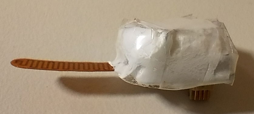
Cover the EIF top with parafilm tape or silicone sealant to protect it from debris.
Notes:
Do not close the scalp incision by suturing the skin together around the connector. Glue the edges of the scalp incision to the skull with cyanoacrylate, leaving an oval opening for the connector. Create a head fixture out of dental cement within the oval opening.
You will not attach the HMT until after the animal recovers from surgery. The EIF will be sitting exposed on the animals head for a few days. This is why we cover the EIF with parafilm or sealant after implantation.
Surgical Recovery
Allow several days of recovery in a qiet, clean environment.
Monitor for pain, distress, weight loss, or infection.
Consult your vet for protocols on antibiotic treatments.
If the dental cement cap detaches or electrodes become exposed, consult a vet immediately.
HMT Attachment
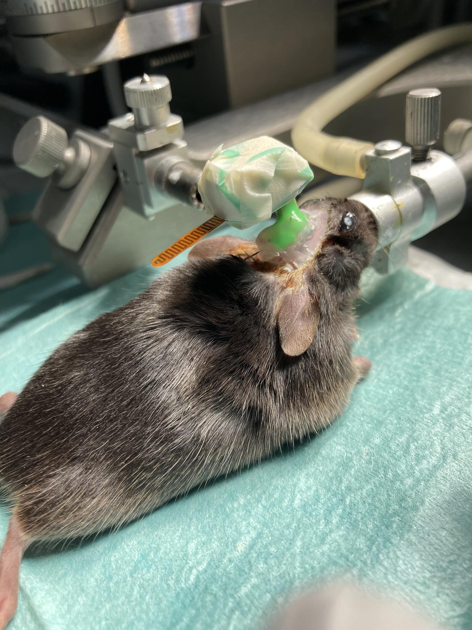
Figure: The HMT Attached to a Mouse Head. Note the green silicone sealant we use to fasten the HMT and EIF connectors together.
Remove a fresh HMT battery from its packaging.
Touch a grounded metal object to dissipate your body's electrostatic charge.
Load the battery into the HMT's battery clip, positive side up.
Confirm the HMT is transmitting on the channel numbers you expect.
 Head-Mounting Transmitter Surgical Protocol