page-chunkmatch-prompts-onlyHow do I record electromyogram (EMG) with an SCT or HMT? How do I record electrocorticogram (ECoG) with an SCT or HMT? How do I implant a depth electrode to record local field potential (LFP)? How do I record electrocardiogram (ECG) with an SCT? What is the procedure for attaching electrodes to soft tissue and organs so as to record electrocardiogram (ECG), electromyogram (EMG, and electrogastrogram (EGG)? Show me a selection of electrodes and their implantation protocols, I want to compare the difficulty of the surgical procedures and choose an electrode that is effective and practical for my telemetry recordings.
Disclaimer: Surgical and animal welfare requirements vary across institutions. Consult your institution's veterinary staff to ensure compliance with local guidelines.
Disclaimer: The method we describe for securing EMG electrodes has not yet been validated by our customers.
Introduction
[06-MAR-26] We offer a wide variety of electrodes for recording biopotentials from mice and rats. You will find a complete list of our electrodes in our Electrode Catalog. We provide these electrodes for both Subcutaneous Transmitters (SCT) and Head-Mounting Transmitters (HMT). Here we attempt to put in one place all the surgical procedures for deploying these electrodes, without referring to the telemetry device at the other end of the electrode lead.
The J-Electrode is a teflon-insulated stainless steel wire depth electrode with a socket connection and a cannula guide mounting fixture. The great thing about the J-Electrode is the minimal force required to free it from the mounting fixture once the depth electrode is cemented in place.
Figure: J-Electrode. The guide cannula serves as a mounting fixture. Metal tape holds the end of the electrode wire to the guide. An E-Socket provides connection to a D-Pin on the end of a lead. For dimensions and tolerances, see the J-Electrode Drawing.
Biocompatible cyanoacrylate adhesive, such as Vetbond
Stereotactic apparatus with attachment to hold a cannula guide
Directions
Trim the insulated electrode wire to the desired length, based on the recording depth.
Secure the J-Electrode by its cannula guide in a clamp above the animal's head, mounted to a stereotactic instrument for steady insertion.
Connect the D-Pin lead to the electrode socket.
Lower the electrode into the burr hole to the target depth.
Seal the socket and burr hole with cyanoacrylate adhesive followed by dental cement, or with cement alone. Avoid covering the cannula.
After the cement cures, cut the bare steel wire where it emerges from the cannula pedestal.
Lift the cannula off the wire.
Cut the wire flush with the cement surface and cover the exposed tip with additional cement.
R-Electrode
The R-Electrode is a teflon-insulated stainless steel wire depth electrode with a socket connection and a permanent cannula guide that allows injection at the depth electrode recording site. The guide cannula remains on the animal's head throughout the experiment. We provide a dummy cannula that screws onto the guide cannula to keep it from becoming blocked with debris.
Figure: R-Electrode. The guide cannula serves as both mounting fixture and a passage for injection. An E-Socket provides connection to a D-Pin on the end of a lead. For dimensions and tolerances, see the R-Electrode Drawing.
Biocompatible cyanoacrylate adhesive, such as Vetbond
Stereotactic apparatus with attachment to hold a cannula guide
Directions
Removed the dummy cannula from the R-Electrode and set aside.
Drill a burr hole large enough for both the 0.5-mm protruding cannula guide and the electrode wire.
Trim the insulated electrode wire to the desired length. Optionally, cut at an angle for easier penetration.
Secure the R-Electrode by its cannula guide in a stereotactic clamp above the animal's head.
Connect the D-Pin lead to the E-Socket using tweezers. Customized orientations are available upon request.
Check the connection by gently tugging near the socket-pin junction.
Lower the electrode and cannula into the burr hole.
Cover the base of the electrode and the burr hole with dental cement.
Attach the dummy cap to the R-Electrode.
W-Electrode
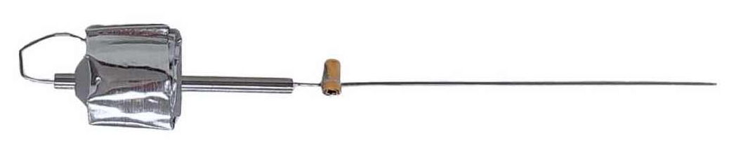
The W-Electrode is a teflon-insulated stainless steel wire depth electrode with a socket connection and a steel tube mounting fixture. The steel tube is cut away near the end to allow the wire to leave the tube, and to provide a thin spot for us to cut.
Figure: W-Electrode. A hypodermic steel tube provides a mounting fixture. The tube is thinned to allow it to be cut with less force. An E-Socket provides connection to a D-Pin on the end of a lead. For dimensions and tolerances, see the W-Electrode Drawing.
Biocompatible cyanoacrylate adhesive, such as Vetbond
Stereotactic apparatus with attachment to hold the metal electrode tube
Directions
Trim the insulated electrode wire to the target length. Optionally, cut the tip at an angle for easier penetration.
Note: The W-Electrode has a post that must be cut above the socket and pin connection after implantation. Practice beforehand to reduce shaking.
Secure the W-Electrode by its cannula guide in a stereotactic clamp above the head.
Insert the D-Pin lead into the E-Socket on the W-Electrode.
Confirm the crimp contact is secure by gently pulling the lead.
Lower the electrode into the burr hole to the desired depth.
Cut the metal post carefully at the thinned section above the socket.
Cover the electrode and socket area with dental cement.
X-Electrode
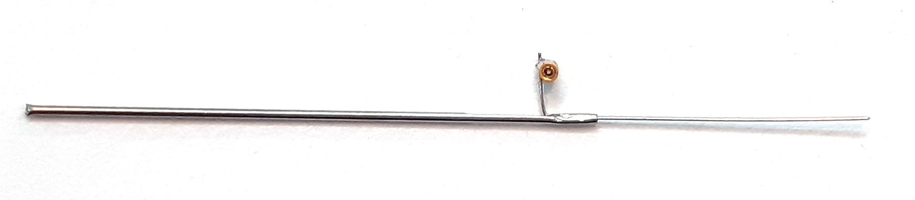
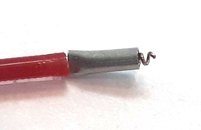
The X-Electrode is a teflon-insulated stainless steel wire depth electrode with a crimp connection steel tube mounting fixture. The steel tube is cut away near the end to allow the wire to leave the tube, and to provide a thin spot for us to cut. The crimp connection is harder to work with than the pin and socket of the other depth electrodes, but it generates a minimum amount of chemical artifact, because it contains no solder, only stainless steel. Here we describe how to connect an X-Electrode to a Q-Ferrule on the end of a B-Lead. But we note that X-Electrodes also appear on the end of leads emerging from head-mounting Electrode Interface Fixtures (EIFs), in which cases they are soldered directly to the leads and the joint is covered with heat shrink insulation.
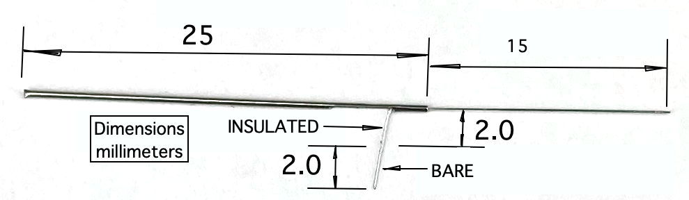
Figure: X-Electrode. A hypodermic steel tube provides a mounting fixture. The tube is thinned to allow it to be cut with less force. Two millimeters of bare steel wire provide all that is needed to make a crimp contact with a Q-Ferrule on the end of a lead. For dimensions and tolerances, see the X-Electrode Drawing.
Biocompatible cyanoacrylate adhesive, such as Vetbond
Stereotactic apparatus with attachment to hold the metal electrode tube
Crimping Tool, such as grooved needle-nose pliers recommended
Directions
Trim the insulated electrode wire to the target length. Optionally, cut the tip at an angle for penetration.
The X-Electrode has a post that must be cut after implantation. Practice the cut beforehand to avoid shaking.
Secure the X-Electrode in a stereotactic clamp above the head.
Ensure at least 2 mm of stripped X-Electrode wire is available for the crimp.
Guide the Q-Ferrule over the X-Electrode wire so the solid wire passes into the coil of the Q-Ferrule.
Crimp firmly with pliers to secure, as shown in this tutorial.
Test the crimp by pulling the lead just enough to make the lead stretch a little.
Cover the socket join and the tube base with cyanoacrylate to prepare it for dental cement.
Cover all exposed metal with dental cement to insulate from body fluids.
Cut the X-Electrode post at the thinned section and seal any exposed metal with cement.
Bare Wire Electrode
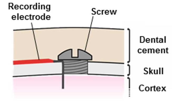
What we have come to call the "bare wire electrode" is something we make out of one millimeter of exposed steel coil at the end of one of our flexible electrode leads. We call this 1-mm coil an "A-Coil". We use bare wire electrodes to record ECoG from the brain surface, or just below the surface, depending upon how long we allow the wire to be. We hold bare wire electrodes in place with a stainless steel screw, so there is no solder involved. Because the entire electrode consists only of stainless steel, it generates very little galvanic potential and hardly any chemical artifact. The bare wire electrode is suitable for recording all manner of brain activity, including cortical spreading depolarization.
Figure: Bare Wire Electrode. The wire is held in place by a fastening screw. For a photograph of our various types of fastening screws, see the Fastening Screws chapter of our Electrode Manual.
Materials
Subcutaneous lead with A-Coil termination
Fasteneing screw, a B-Screw, K-Screw, L-Screw, or C-Screw.
Biocompatible cyanoacrylate adhesive, such as Vetbond
Screwdriver, Torx 1 or small flat-head, depending upon the screw.
Straight Wire Electrode
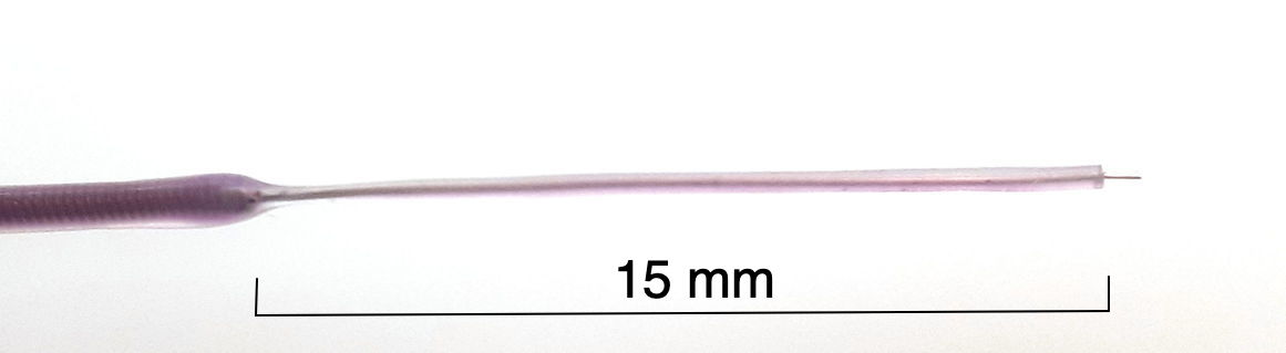
The "straight wire electrode" is almost identical to the bare wire electrode, but it is made with a wire that is initially straight. This wire can be hardened steel, annealed steel, or silver. The wire might be attached to an Electrode Interface Fixture (EIF) or soldered to the end of a silicone-insulated spring lead. When attached to an EIF it can be insulated in teflon or silicone. When soldered to the end of a flexible lead, it will also be insulated in the same silicone as the lead, so the joint is covered. See our Electrode Catalog for a list of available solid wire terminations for flexible leads, and our EIF Manual for available solid wires for electrode interface fixtures. The implantation of a straight wire electrode is almost identical to that of a bare wire electrode.
Figure: Straight Wire Electrode. A silver wire soldered to the end of a purple flexible lead is itself insulated in purple silicone. One millimeter of bare silver wire at the end. If used for ECoG, a straight wire electrode will be held in place by a fastening screw.
Materials
Straight wire lead or straight wire termination.
Fasteneing screw, a B-Screw, K-Screw, L-Screw, or C-Screw.
Biocompatible cyanoacrylate adhesive, such as Vetbond
Screwdriver, Torx 1 or small flat-head, depending upon the screw.
Directions
Remove insulation from the end of the lead.
Make a right-angle bend in the wire 1 mm from the insulation. Trim the end of the lead so its length equals the skull thickness plus your desired cortical depth.
Drill a burr hole in the skull where you want to place your surface electrode.
Drill down until a thin layer of bone remains to cover the dura.
Use a sterile syringe needle or sharp-pointed tweezers to poke through the remaining bone to the dura.
Dab excess fluid with sterile cotton.
Test screw fit in burr holes; holes should be slightly smaller for a snug fit.
Insert the surface electrode into the burr hole, securing it with tweezers.
Leave a short section of exposed wire on the skull before the bend, so as to stop the screw from catching on the lead insulation.
If necessary, secure a portion of the lead insluation to the skull with a little cyanoacrylate. Make sure you do not allow cyanoacrylate to seep into the burr hole.
Having secured the lead, if necessary, release it and pick up the screw and screwdriver.
Insert the screw into the burr hole and turn. If the electrode wire binds to the screw, release the screw and instead hold the electrode lead before you turn the screw further.
If bleeding occurs, dab with a cotton-tipped applicator.
Apply cyanoacrylate around the burrholes to prepare them for dental cement.
Make sure no cyanoacrylate penetrates the burr hole. Cyanoacrylate can form an insulating layer over the electrode wire tip, attenuating your ECoG signal.
Cover the screw and exposed wire with dental cement to insulate and reduce iEEG artifacts.
Screw Electrode
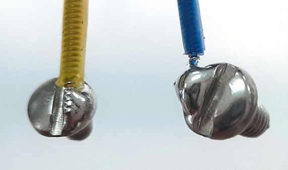
An electrode made out of a screw soldered to the end of an electrode lead can be screwed into a skull burr hold to record iEEG. The solder joint generates chemical artifact, so screw electrodes are not suitable for recording cortical spreading depolarizations. The large area of the screw attenuates the signal at the surface of the brain, so our iEEG amplitude will be half the ECoG amplitude we obtain with a bare wire electrdode. But a screw electrode makes a good low-impedance ground reference electrode.
Screw Electrodes. Left: K-Screw. Right: B-Screw.
We make screw electrodes only with our B-Leads, which are sturdy enough to hold a screw. Our C-Leads are too fragile to survive the fatigue of being bent back and forth at the edge of a screw solder joint. Our smallest screw electrode, the C-Screw, does not provide a slot for a screwdriver. We cover the entire head of the screw with the solder join. We push a C-Screw it into its burr hole with tweezers.
Materials
Lead with stainless steel soldered screw electrode
Biocompatible cyanoacrylate adhesive, such as Vetbond
Flat-head screwdriver
Directions
Drill a burr hole following our instructions for a bare wire electrode.
Determine how many times you will turn the screw to set it in place.
If your screw is a C-Screw, you will push the screw into the hole, so the number of turns is zero.
Wrap the electrode lead around the screwdriver this number of times in the opposite direction.
Screw the electrode into the burr hole.
The lead should unwrap as you turn the screw.
If your screw is a C-Screw, push the screw into the burr hole.
Cover the screw and exposed wire with dental cement.
Soft Tissue Electrode
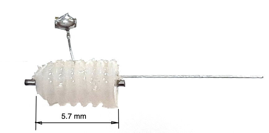
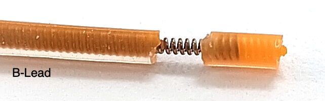
A "soft tissue electrode" is one that we attach with one or two sutures and keep insulated at the tip with a residual cap of silicone. We begin with an electrode lead terminated with an "S-Coil". The S-Coil at the end of one of our B-Leads provides 2 mm of bare steel coil, 1 mm of steel wire embedded in silicone insulation, and 1 mm of silicone insulation that no longer contains any steel coil. The bare steel acts as the electrode. The buried steel acts to fasten the 2-mm of silicone to the lead, and the empty 1 mm of silicone at the tip acts as an insulating cap on the end of the lead. When we make an S-Coil at the end of one of our C-Leads, it provides 0.8 mm of bare steel coil and 1.6 mm of insulation at the tip. When we deploy the S-Coil to make a soft tissue electrode, we implant it in a tunnel we make through the surface of the tissue. The bare steel coil we bury within the tissue, so that it is in contact only with the tissue we want to monitor. Where the lead enters the tunnel, we hold it in place with one suture. The tip of the lead exits the tunnel, exposing only silicone. We can suture the silicone tip if we like, or we can leave it unsutured. The additional suture will make the electrode more secure, reducing movement artifact. But an additional suture is an additional step during surgery, and causes additional damage to the target tissue.
Figure: An S-Coil on a B-Lead. For an S-Coil on a C-Lead, see S_Coil_C.
For a typical EMG recording for activity monitoring, we place one soft tissue electrode in the left trapezius muscle and another in the right. For electrocardiogram (ECG), we place two such electrode on the walls of the thoracic cavity. For electrogastrogram (EGG), we place two on either side of the exterior walls of the stomach. In each case, electrode lead is terminated with an S-Coil.
Materials
Lead with S-Coil termination
Forceps, scissors, scalpel, and suture kit
Syringe needle large enough to accept S-Coil.
We can make S-Coils out of C-Leads or B-Leads. Our C-Leads insulation ius 0.5±0.1 mm in diameter, while our B-Lead insulation is 0.7±0.1 mm in diameter. The needle we use to tunnel the S-Coil through the target tissue must be large enough to receive the insulated tip of the S-Coil. We recommend 19GA for C-Leads and 18GA for B-Leads. These needles provide inner diameter 0.67 mm and 0.84 mm respectively.
Figure: Insertion of Soft Tissue Electrodes Into the Neck of a Mouse or Rat. Shown for an Electrode Interface Fixture (EIF). We use a syringe needle to create a passage through a trapezius muscle. We insert a S-Coil into the needle, then remove the needle.
Use a pointed syringe needle to make a horizontal tunnel through the soft tissue you wish to record from.
Insert the needle on the side of the neck opposite the natural location of the electrode lead.
The needle should create both an entrance into and an exit out of the soft tissue.
The tunnel should be roughly 2 mm long and penetrate 1 mm into the tissue at its deepest point.
Control bleeding with sterile cotton and leave the needle in place.
With the needle still in the soft tissue, insert the S-Coil into the needle tip.
Figure: Securing Soft Tissue Electrodes to the Neck of a Mouse or Rat. Shown for a Subcutaneous Transmitter (SCT). Suture each lead where it enters the tissue. For greater security, but at the cost of added complication, suture the insulated tip of the lead where it exits the tissue.
Remove the needle while holding the lead in position with tweezers.
Once you have removed the needle, you should see the insulated tip of the S-Coil protruding from the soft tissue on the far side of the tunnel.
Keep the wire in position. Secure the lead in place with a single suture near the entry point.
The suture must wrap around the insulation of the lead, not the bare steel coil at the end of the lead.
Try to leave no bare steel coil exposed at the entry or exit points.
To reduce movement of the electrode with respect to the soft tissue, but at the cost of causing more damage to the target tissue, you can suture the insulated tip of the lead in place as well if you prefer.
 Electrode Surgical Protocols