Contactless Position Measurement System |
Contactless Position Measurement System |
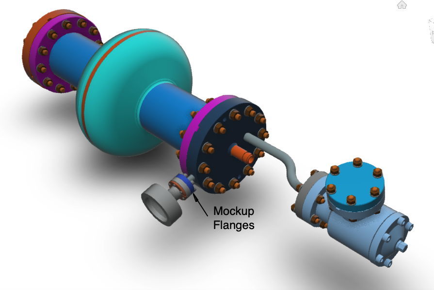
[18-MAR-24] The particle accelerators and fusion reactors that will be built in the next twenty years make liberal use of precision-machined, highly-reflecting metallic components. In the case of the particle accelerators, we must not handle the components during assembly, or else we will contaminate their surfaces and ruin their performance. In the case of fusion reactors, we must handle the components as little as possible to avoid radiation sickness. In order to bring these components into contact and line up their bolt holes, we need an instrument that measures their relative positions and moves them together correctly. Traditional front-illuminating machine vision systems cannot locate highly-reflecting components accurately. In this Phase I SBIR project, funded by United States Department of Energy tracking number GRANT13557088, Award DE-SC0022581, we built an accurate and effective Contactless Position Measurement System (CPMS) for highly-reflecting components. We place infrared backlights behind the components and take two silhouette images of the components from two different locations. These stereo images allow us to apply the principles of triangulation, parallax, and scale to deduce the location and orientation of each component. At a range of 50 cm, we are able to measure the relative positions of two stainless steel flanges with an accuracy of 150 μm rms. This measurement can take place in a clean room with no humans present and is effective even with bright overhead illumination in the room.
[19-MAR-24] Our Contactless Position Measurement System (CPMS) makes it possible to perform automatic alignment of highly-reflecting components. As described in Clean Room Automation of SRF Cavity String Assembly, there are times when highly-reflecting components cannot or should not be touched by human hands. During Superconducting Radio Frequency (SRF) string assembly, human contact causes contamination, and contamination spoils the resonance of the cavities. During maintenance of fusion reactors, the components we remove from the reactor are radioactive. The length of time for which humans can handle the components in order to carry out repairs is limited. We would like to measure the relative positions of such objects so we can bring them into alignment with motorized stages. We would like to make our measurement without touching the objects. But measuring the location of highly-reflecting objects is challenging.
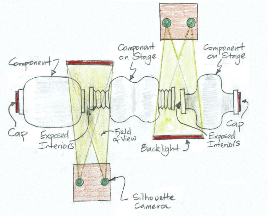
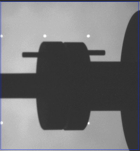
The CPMS uses an infrared background and stereoscopic cameras to capture infrared silhouette images of two or more components in its field of view. The background for the silhouette images is an infrared panel. The cameras are equipped with infra-red only filters. We call them Silhouette Cameras (SCAMs). Reflections of fluorescent and solid-state lamps do not affect our silhouettes because they contain almost no infrared light. The CPMS analysis software combines the silhouette images with knowledge of the dimensions of the objects to obtain the relative positions of components in its field of view. At a range of 50 cm, and without taking multiple measurements in the same position, the CPMS is accurate to 50 μ rms in the transverse directions and 300 μm in the longitudinal direction. If we take the average of ten measurements, our accuracy to better than 50 μm transverse and 150 μm longitudinal.
The CPMS measures position and orientation, which together we call its pose, with respect to its own calibrated reference plate. Because the components the CPMS will view are machined out of highly-reflecting metals, we know their dimensions to within a ±125 μm (5 mils). The CPMS takes stereo silhouette images of the components, combines the images with our knowledge of the component dimensions, and so deduces the pose of each component, provided that some portion of each silhouette is evident in the SCAM images. The CPMS measurement of position and orientation allow us to maneuver the components into contact using motorized stages. Once the components are in contact, the risk of contamination of their interiors is greatly reduced, and the time taken to complete their attachment is greatly reduced.
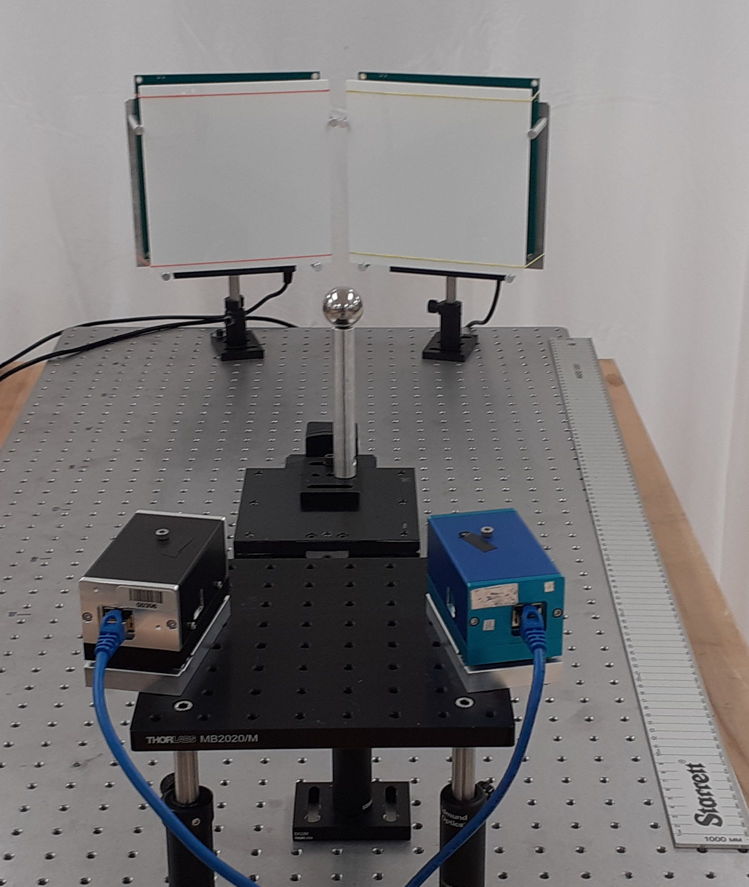
An SCAM is similar to the well-established Boston CCD Angle Monitor (BCAM), but with a larger field of view and correspondingly lower precision. Each SCAM mounts on three balls in exactly the same way as a BCAM. The CPMS plate holds two SCAMs and defines its own coordinate system. We calibrate the plate by moving a sphere around in front of the SCAMs, taking images of the sphere, and at the same time measuring its position with our Coordinate Measuring Machine (CMM). This calibration procedure allows us to calibrate both cameras so that we can project modeled objects accurately from the global CPMS coordinate system one the two SCAM image sensors.
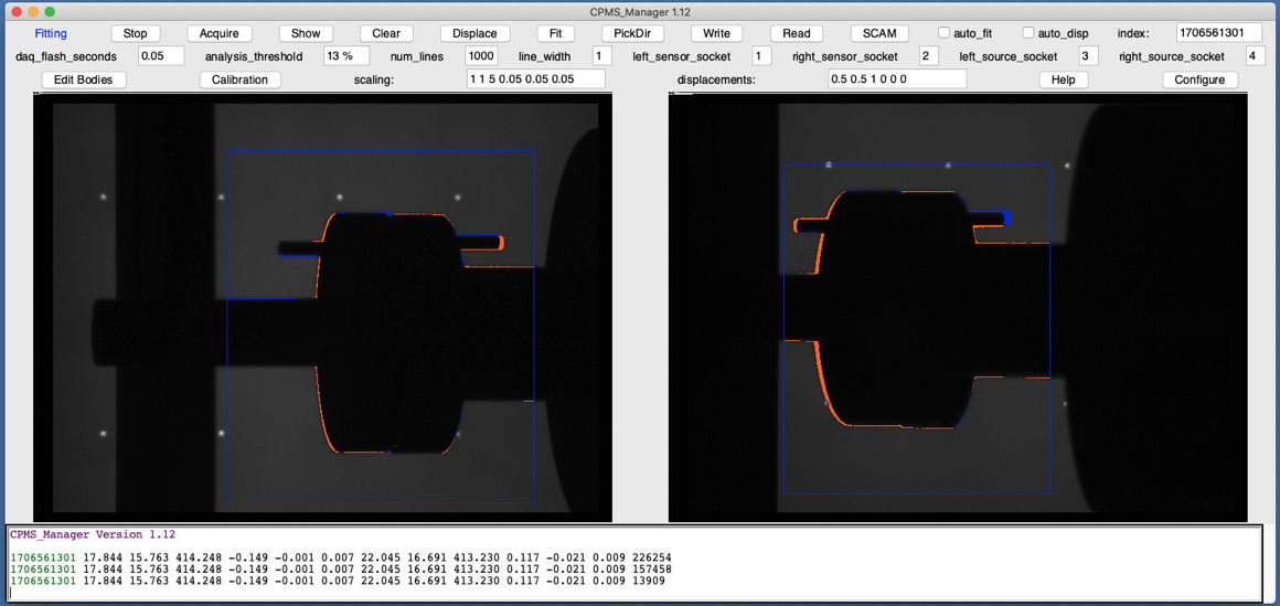
To measure the location of a component we begin with a silhouette image, guess the approximate location of the component and project a model of the component onto our image. Our purpose is not to measure the size or shape of the component, but rather to determine the pose of a component whose size and shape we already know. We count the pixels in the image where the modelled silhouette and the actual silhouette disagree. We adjust the model pose until we minimize this disagreement. The final pose of the model is our measurement of the pose of the actual component.
Development of the CPMS was funded by the United States Department of Energy (DoE) under SBIR Phase I Award DE-SC0022581. With the Phase I grant, we solved all the technical challenges required to build a CPMS. Our application for further funding in Phase II to develope a larger, motorized CPMS received favorable reviews but was nevertheless declined. We now offer custom-made CPMS instruments for sale. Our customer specifies the nominal operating range of the instrument to be anywhere from 50 cm to 200 cm. We can provide the CPMS as a basic measurement-only system with stereo cameras and backlight, or equipped with a motorized translation and rotation stage that will align two components automatically with the help of CPMS measurements.
[10-JUN-25] Here are further documents describing the DFPS development, design, and history.