| Description |
| Design |
| Circuit Operation |
| Design |
[24-SEP-25] The A3026 H-BCAM Side Head is the circuit that we load onto the front and back walls of an H-BCAM chassis to provide its light sources. A BCAM (pronounced "beecam") is an optical surveying instrument (Boston CCD Angle Monitor). The A3026 is an extension to the A3025 BCAM Head. It provides two laser diodes in 5.6-mm metal packages (such as the L650P007) and one array of four LEDs in 3-mm plastic packages. The A3026 is designed for use in both BCAM-HL Black H-BCAMs and BCAM-HR Blue H-BCAMs. The H-BCAM was dewsigned for use in the HIE-ISOLDE Alignment System, but has been deployed in many other systems since then. The H-BCAM is the only BCAM to provide a white-light flash to illuminate retroreflecting targets with incoherent light.
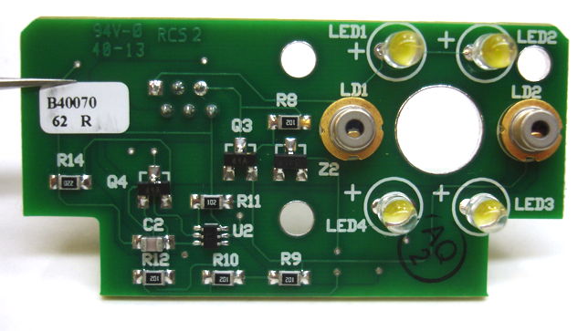
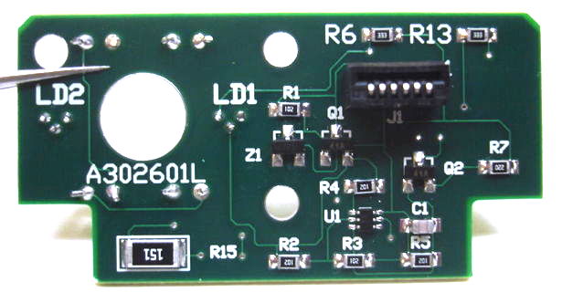
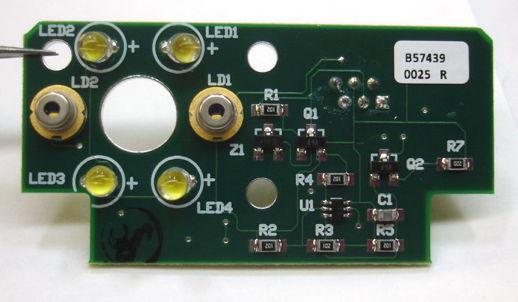
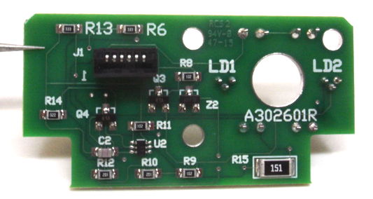
The A3026L is the side head for the Black (left-handed) version of the H-BCAM. The A3026R is for the Blue (right-handed) BCAMs are mirror images of one another. The laser drivers in the A3026 are identical to those developed and studied in the A2074 Laser Head, but the orientation of the single-sided flex connectors we use in the A2074C and A2074D are opposite those of the A3026L and A3026R, so that we cannot unplug an A2074C/D from its flex cable and use the same flex cable to drive an A3026L/R.
The bottom side of the A3026 H-BCAM Side Head provides a six-way flex connector for a flex cable that joins it to its A3025 BCAM Head. The following figure shows what is inside the BCAM-HL. On the front and rear walls are two A3026A BCAM Side Heads. The circuit board screwed to the base of the chassis is a A3025A BCAM Head. The image sensors are mounted on A2076D ICX424 Minimal Heads.
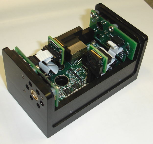
The two A3026s in an H-BCAM connect to the A3025 with two 50-mm, 6-way flex cables. The six pins of the flex cable carry three 0-15V power controls for the two lasers and the LED array. On the A3026 there are two laser driver circuits, which control the current through the lasers so as to maintain constant output intensity. The LEDs are connected in series through a dissipation resistor. We use either blue or white LEDs for the flash array. The blue LED is the most efficient at producing light power per milliamp of forward current. A white LED is a blue LED with yellow phosphor on top. In either case, assembly of the BCAM is easier if we can put the LEDs into their footprints after we have screwed the A3026 in place. Thus we prefer LEDs without a base flange, because these we can insert through LED's chassis hole from the outside. Examples are the VLHW4100 white LED or the OVLBB4C7 blue LED.
| Version | Description |
|---|---|
| 3026A | Prototype Black H-BCAM Side Head, 5-mW 650-nm sources, 22-mA white LEDs |
| 3026B | Prototype Blue H-BCAM Side Head, 5-mW 650-nm sources, 22-mA white LEDs |
| 3026L | Black H-BCAM Side Head, 5-mW 650-nm sources, 22-mA white LEDs |
| 3026R | Blue H-BCAM Side Head, 5-mW 650-nm sources, 22-mA white LEDs |
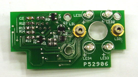
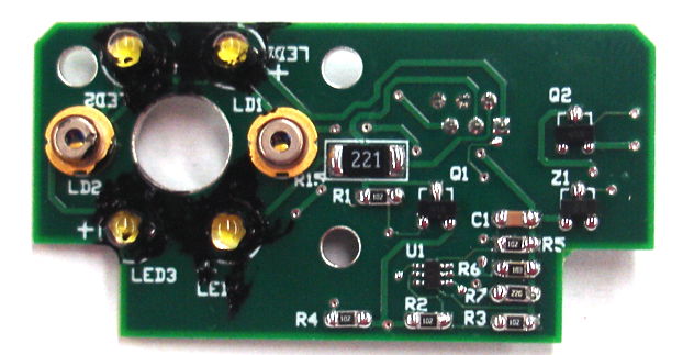
The output power of the two lasers is set by resistors R7 and R14. The power of LD1 is set by R7 and of LD2 is set by R14. In the first 70 A3026R and 70 A3026L we used the 7-mW L650P007 laser and we chose R7 and R14 for each laser to set its output power in the range 5-6 mW. In the next 30 of each type we used the 7-mW ADL65074TL1 laser and again chose R7 and R14 to set the output power to 5-6 mW. Any time the power is 5 mW or greater, we need a laser warning label on the side of the BCAM.
[17-JUL-25] The following files describe the design of the A3026 H-BCAM Side Head.
S3026_1: Laser Drivers and LED Array.
A3026LV1.ods: BOM and PIK for Black H-BCAM Side Head.
A3026RV1.ods: BOM and PIK for Blue H-BCAM Side Head.
A302601B.zip: Gerber files for A302601B PCB for BCAM-HLD.
A302601C.zip: Gerber files for A302601C PCB for BCAM-HR.
A302601L.zip: Gerber files for A302601L PCB for BCAM-HL.
A302601L_Panel.pdf: Panel drawing 5 x 3 A302601L.
A302601R.zip: Gerber files for A302601R PCB for BCAM-HR.
HBCAM_Rear: Drawing of holes on the H-BCAM wall.
[20-MAR-26] The A3026 H-BCAM Side Head contains two laser drivers. The laser drivers are identical to those provided by the A2074 Dual Laser Head. You will find a detailed description of the laser driver circuit in the A2074 manual. For a more general discussion of laser drivers see the A2049 manual.
We set the equilibrium photodiode, or monitor, current of LD1 with R6. The circuit will increase the laser diode forward current until the voltage across R6 is roughly 3.0 V. Thus with 15 kΩ in R6, the monitor current will be 200 μA. We set the monitor current of LD2 with R13. When we load a new laser, our habit is to load 33 kΩ for the photodiode resistor, measure the laser power, and decrease the resistor so as to set the laser power at the value we desire. With the L650P007 7-mW laser, we find that a photodiode resistor of between 13 kΩ and 16 kΩ gives a 6-mW output. With the L658P040 40-mW laser we use 50 kΩ to 60 kΩ to give 6 mW, and 15 kΩ to give the full 40 mW.
The schematic has photocurrent resistors R6 and R13 marked "TBD" for "to be decided". In the bill of materials, we call for 33 kΩ, which for the red lasers we use in BCAMs, will set the laser power output to below its maximum, allowing us to turn on the laser, measure its power, and calibrate its photocurrent resistor. In the L and R versions of the A3026 circuit board, these two resistors are on the opposite side of the board from the lasers, so they are accessible after the board is installed in a BCAM. This allows us to adjust the power of the lasers after we have soldered them in place.
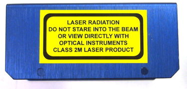
Provided we do not place a lens in front of the A3026 laser diode, the visible light it emits is not dangerous. If the output power is below 5 mW, the laser is said to be Class I, and we don't have to put any safety label on the box. But when we set the laser power to 5 mW or higher, it becomes Class 2M. We should avoid staring at the laser and avoid looking at it through any optical device that might focus the light onto our eye. Furthermore, we need to put a safety label on the box containing the laser diode, as shown below.
The four LEDs of the flash circuit are in series with one another, and with a power dissipation resistor. The resistor limits the current to the LEDs and is large enough to dissipate excess power from the supply. The schematic has power dissipation resistor R15 marked "TBD" also. Resistor R15 is a 0.75-W resistor that limits the current through the four LEDs. If we install the blue OVLBB4C7 LED, its rated forward current is 20 mA at which its forward voltage drop can be as low as 2.6 V and as high as 4.0 V. With 15 V applied to the four LEDs, we will have at least 10.4 dropped across the diodea and much as 16 V. The maximum continuous forward current of this diode is 25 mA. To protect the diodes with the minimum voltage drop, we must use R15 = 184 Ω. Suppose we pick R15 = 180 Ω. The typical diode has forward drop 3.2 V at 20 mA so we will then see only 12 mA in the diode chain. When we buy a bag of these LEDs from Optek, all LEDs in the bag have forward voltage within ±0.1 V. So our best bet is to buy the LEDs and choose the resistor to suit the batch. Resistor R15 is on the side opposite the LEDs on the L and R versions of the A3026 circuit board so we can change it if the LEDs are too bright or too dim.
The VLHW4100 white LED produces a luminous intensity of 8000 mcd in the forward direction at a forward current of 20 mA. Its maximum forward current is 20 mA. Its forward voltage drop at 20 mA is 3.2 V typical. With 220 Ω, we expect 10 mA. With 100 Ω we expect 22 mA.
[19-SEP-25] For design files and development logbook, see the A3026 H-BCAM Side Head design page at D3026.