| Description |
| Set-Up |
| Operation |
| User Programs |
| Version Changes |
NOTE: This manual applies to the Stimulator Tool Version 4.1+, available in LWDAQ 10.6.10+.
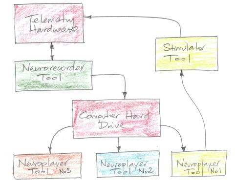
[19-MAY-24] The Stimulator Tool controls our Implantable Stimulator-Transponders (ISTs). It is a component of our LWDAQ Software. The Stimulator Tool monitors IST activity with the help of either a Neuroplayer Tool or a Receiver Instrument. The signals transmitted by an IST are identical to those transmitted by our other telemetry devices, such as our subcutaneous transmitters (SCT), head-mounting transmitters (HMT), and implantable inertial sensors (IIS). Only the IST, however, can respond to telemetry to commands. When we transmit commands to an IST, we use pulses of radio-frequency waves that are thousands of times more powerful than the telemetry signals transmitted by the ISTs themselves.
Each IST is equipped with a crystal radio that receives commands and an oscillator that transmits telemetry messages. We transmit commands to the IST with a command transmitter, such as the A3042B Telemetry Control Box (TCB) or A3029C Command Transmitter. We receive commands with a data receiver. See Set-Up for details. All command transmitters and all data receivers will provide a LWDAQ server for which the Stimulator Tool will act as a client. The Stimulator Tool needs to know the internet protocol (IP) address of the server. If the server provides several LWDAQ driver sockets, the Stimulator Tool needs to know which socket we are using. There are entries for both these values in the Stimulator Window. We select a particular IST with its identifier, or ID. The identifier is written on the body of the IST as a four-digit hexadecimal number. Upon command, the IST will carry out a stimulus. We specify the number of pulses, the length of the pulses, the pulse interval, the strength of the pulses, and whether or not the pulses should be random or regular.
We use the Start button to initiate a stimulus in a particular device. We use Stop to end the stimulus prematurely. We use Xon to start synchronizing signal and Xoff to end it. All ISTs will turn themselves off after a couple of minutes when there is no stimulus running, so pressing Xoff is not necessary. We also have Start_All, Stop_All, and so on to start the same stimuli in all devices, or stop stimuli in all devices, and so on.
The IST uses telemetry auxiliary messages to transmit single messages that acknowledge commands, announce their version number, announce their identifier, and provide battery voltage measurements. With Verbose checked, the Stimulator will report the details of every command we transmit and all responses it obtains from ISTs. The Stimulator uses the responses to set the identifier background green when a stimulus starts and set it to gray when a stimulus ends. It sets the identifier digits to red during a synchronizing transmission and to black at the end of a synchronizing transmission. It uses the responses to update the version number and battery voltage values.
Upon command, an IST will use a telemetry channel to transmit a synchronizing signal. The synchronizing signal embeds the state of the stimulus into our telemetry recording. Positive pulses show when the stimulus current is turned on. The height of the pulses tells us the stimulus current. The synchronizing signal is similar to an SCT signal in that is has a sample rate and an SCT channel number. We set the sample rate and the channel number in the Stimulator Tool. The Stimulator Tool allows us to specify the telemetry channel each IST will use, so that our synchronizing signals do not conflict with those of our other telemetry devices.
When the Stimulator Tool transmits an identify command, all ISTs that receive the command will transmit their identifiers. The ISTs will not transmit all at the same time, but instead will wait for a length of time proportional to their identifier, so that they do not collide with one another. To acquire these signals and auxiliary messages, the Stimulator Tool looks first for a communal Neuroplayer Tool, and looks second for a communal Receiver Instrument. By "communal" we mean that the tool or instrument has been launched within the same LWDAQ process as the Stimulator Tool. We can ensure that the Neuroplayer or Receiver is communal by launching them from the Stimulator Tool using the Neuroplayer or Receiver buttons.
The simplest way to start communicating with a set of ISTs is to use the Receiver Instrument. We configure the Receiver Instrument to download, analyze, and display the live signals from a data receiver. The Stimulator Tool will look in this data for IST auxiliary messages. In any practical application of the IST, howevever, we will be recording biometric signals with a Neurorecorder. If so, we can monitor ISTs in real time by opening a Neuroplayer and playing the telemetry recording as it is written to disk. When we want to re-examine our stimuli and the effect they had upon simultaneous biometric signals recorded by our telemetry system, we use the Neuroplayer to play back the telemetry recording. The Stimulator Tool will report on the start and stop times of the signals using the time of the recording. Note that the Stimulator Tool will look for a Neuroplayer Tool first and a Receiver Instrument second. If it finds a Neuroplayer Tool, it will ignore any existing Receiver Instrument.
We can initiate stimuli by pressing buttons in the Stimulator Tool, but we can also initiate them by executing the stimulus command in response to an event we detect in one of our telemetry signals. By this means, we can implement closed-loop control. The Neuroplayer's Event Classifier can detect events, call an event handler, and so initiate a stimulus. If we want to respond to events that span several intervals, we enhance the event handler so that it becomes a state machine. Three consecutive seconds of electroencephalogram (EEG) identified as "ictal" might cause us to initiate a stimulus automatically. The event handler called by the Event Classifier would look something like this:
LWDAQ_post "Stimulator_start 3C54"
The above command initiates the stimulus defined in the Stimulator Window. If we want to define the stimulus in our event handler, we can do so with:
set Stimulator_config(pulse_ms) "10"
set Stimulator_config(period_ms) "100"
set Stimulator_config(num_pulses) "10"
set Stimulator_config(current) "8"
set Stimulator_config(sps) "512"
set Stimulator_config(random) "0"
LWDAQ_post "Stimulator_start 3C54"
In addition to its built-in stimulus and synchronizing functions our implantable stimulators will run programs we write ourselves. We describe how we can write, upload, and run our own algorithms in the User Programs section below.
[25-MAY-26] To operate ISTs, we can use one of two systems. By far the most effective system, and the one that is easiest to deploy, is an A3042B Telemetry Control Box (TCB). The A3042B-series TCBs provide four or sixteen coaxial antennas inputs, all of which transmit commands simultaneously, and when they are not transmitting commands, are all deployed for telemetry reception, in which task they are all independent. Our original IST control system used the A3029C Command Transmitter, which must be deployed together with an A3027E Octal Data Receiver (ODR) and an A2071E LWDAQ Driver. This older system provides only one command transmitting antenna, so its command reception range is shorter. Because it consistes of three instruments rather than just one, it is also more difficult to set up. Follow the SCT set-up instructions for a Telemetry Control Box, and your hardware is ready to go.
Once we have our system hardware connected together, we download and install the latest version of LWDAQ. In the Tool menu, we select the Neurorecorder. A new window opens, providing an independent Neurorecorder. We use this program to record telemetry signals from our SCT system. The Neurorecorder writes these signals to files on disk in our NDF format. Only the Neurorecorder writes to the file on disk, and it runs in a process of its own on the data acquisition computer. We go back to our original LWDAQ process and select Stimulator from the Tool menu. The Stimulator Tool opens. We use its Neuroplayer button to open a Neuroplayer. We set the Neuroplayer up to play the data being written to disk by the Neurorecorder. We play the live data file. The Neuroplayer will display SCT signals as well as IST synchronizing signals. The Stimulator will find auxiliary messages transmitted by the ISTs in the live recording and report them to its own text window.
If you have our original stimulator control system hardware in your laboratory, consisting of a Command Transmitter (A3029C), Octal Data Receiver (A3027E), and LWDAQ Driver (A2037E or A2071E ), consult the Set-Up chapter of our Telemetry Manual for instructions on setting up the Octal Data Receiver (A3027E) and LWDAQ Driver (A2071E or A2037E) for telemetry reception, and then add the Command Transmitter (A3029C). Plug the A3029 into one of the driver sockets on the front of the LWDAQ Driver (A2037E or A2071E). The Stimulator Tool is by default configured to target driver socket eight, so we recommend plugging the A3029C into the driver socket farthest from the indicator lights, while the A3027E will be plugged into the driver socket closest to the indicator lights, this being driver socket one, which is the default target of the Receiver Instrument used for telemetry reception. Once you have the A3029 connected to the LWDAQ Driver, it receives minimal power for operation, and it can receive and obey instructions sent to it by the Stimulator Tool. In order to boost the power of the transmitted commands, however, we should in addition connect a boost power supply to the A3029, which is a dedicated 24-V power adaptor with a 5.5-mm power jack. This power adaptor might be identical to the power adaptor you are using with your LWDAQ Driver, or it might be smaller. If you have a larger and smaller 24-V power adaptor, use the larger one for the LWDAQ Driver and the smaller one for the A3029C boost power input. Connect the boost power adaptor to the power jack on the side of the A3029C chassis.
Command reception from the A3029C is less reliable than from a TCB. The A3029C provides only one command transmission antenna, while the A3042B-16 TCB provides sixteen independent transmission antennas. We can, in principle, split the A3029C transmit signal using a coaxial radio-frequency splitter, such as the one-to-four ZB4PD1, and connect four commant transmission antennas to a single A3029C. But when we split the signal in this way, the radio frequency waves transmitted by all four antennas will be coherent. Coherent signals interfere with one another, which causes complete cancellation of of the command transmission in certain locations in our telemetry volume. These reception dead spots will undermine command reception from the A3029. The TCB-B16, on the other hand, transmits slightly different frequencies on all sixteen of its transmit antennas. These differences in make it impossibly unlikely that multiple command transmissions will cancel by destructive interference at the same location in our telemetry volume. We recommend that you upgrade your telemetry system to a TCB if you plan any major study with ISTs.
[19-SEP-23] To communicate with an IST we must know its identifier (ID). The identifier is a number between 0 and 65535. Instead of writing the number as a decimal value, we write it as a four-digit hexadecimal value. So the identifier could be "A123" or "7431". The latter may be confused with a decimal number, so we prefer to write "0xA123" and "0x7431", where "0x" means "hexadecimal". The identifier of each IST is written on a label on its body. We can discover the identifiers of all IST within range of our command antenna by transmitting an identify command and waiting for their responses. We press the Stimulator's Identify button and wait for identifier messages to appear in the text window, each message reporting an identifier. The identifier "0xFFFF" is a "wildcard" identifier. We can specify 0xFFFF either with "FFFF" in the identifier entry box of one of our devices, or we can use a "*" character. When we send commands with the wildcard identifier, all ISTs in range respond at the same time. We may find that we do not receive their acknowledgements because the acknowledgements collide.
We can compose a device list consisting of these ISTs and control them each with their own Start, Stop, Xon, and Xoff buttons. We prepare a list of ISTs with the Add_Device button. We enter our IST identifier. We can save the list to disk and load the list from disk. If we save a list and also save the Stimulator configuration, the Stimulator will read the list automatically the next time it starts up. We remove devices with the X button at the end of each device entry.
When an IST transmits a synchronizing signal, it must use an SCT channel. We can configure the IST to use channel number 1-254, except we cannot use any number for which the remainder is either zero or fifteen when divided by sixteen. Thus we can us 1-14, 17-30, etc. Our SCTs always ship with channel numbers no greater than 222, so we can choose channel numbers 225 and higher for our ISTs and be sure they will not collide with an SCT. We specify the synchronizing signal channel in the channel entry of each device in our device list.
The Stimulator Tool does not turn on its green stimulus indicator, or turn on its red synchronizing indicator, just because we press the Start or Xon buttons. The Stimulator Tool waits until it receives the acknowledgement of these commands before it adjusts the indicators. If an acknowledgement fails, the indicators will remain fixed. The IST uses auxiliary messages to acknowledge commands, transmit battery measurements, and announce its identifier and version number. Set the show_aux flag in the Configuration Panel to get the Stimulator Tool to show you all the auxiliary messages it finds. When an IST transmits an auxiliary message, it uses the lower byte of its identifier as its channel number. It may be that this channel number is the same as the channel number used for another telemetry signal, but any such ambiguity will be resolved through the use of multiple auxiliary messages and timing. The IST always transmits two auxiliary messages one after the other. The first message contains some information, such as a version number. The second acts as a confirmation, and also contains the upper byte of the identifier.
Not only do we get to choose the channel number of an IST's synchronizing signal, we also get to specify its sample rate. The sample rate can be anywhere from 128 SPS to 1024 SPS. We recommend you use sample rates that are an even power of two, but the IST will allow any sample rate, and will do its best to transmit at the rate you request. Press Xon to start the transmission and Xoff to stop. When the IST transmits its synchronizing signal, it twenty times more current than it when it is asleep. All ISTs will turn off their synchronizing signal automatically a few minutes after the end of a stimulus so as to avoid running down its battery.
We specify an IST stimulus with a number of pulses, a pulse length, a pulse interval, a current code, and a selection of regular or irregular pulses. The pulse interval is the average time between pulses. If the pulses are regular, the time between pulses will be equal to the interval every time. If the pulses are irregular, which we select with the Random button, the pulse will be delayed by a random amount of time within its interval, subject to the end of the pulse never overlapping the start of the next interval. Regular and irregular pulses have dramatically different frequency spectra, as shown below.
We specify the pulse interval and pulse length in milliseconds. A pulse length of 10 ms combined with an interval of 100 ms gives 10-ms pulses at 10 Hz. The stimulator specifies pulse and interval lengths in milliseconds with unsigned sixteen-bit values. The minimum length of pulse for an A3041 IST is 2 ms and the minimum interval length is 4 ms. The length of pulses and intervals can be up to 63 ms. The number of pulses is likewise a sixteen-bit number, and can be anywhere from 1 to 65535. If we specify 0 for the number of pulses, the stimulus will go on forever. The current code is a four-bit number from 0 to 15 that determines the stimulus current. The A3041A has the following relationship between current code and current.
The stimulus current is subject to the constraint that the IST has a maximum voltage it can apply to its stimulus leads, and these leads have some internal resistance also. The A3041A with 45-mm leads has total lead resistance 50 Ω and a stimulus voltage of 3.3 V. If we connect the stimulus leads to a blue LED with forward voltage 2.9 V, we will see 8 mA flowing into the LED. IF we connect the ends of the leads together, however, we will see whatever current the IST is set to deliver, which is anything from 0 mA to 10 mA in the case of the A3041A.
[29-OCT-25] Our implantable stimulators permit us to upload a user program that the stimulator will execute with a fixed execution period. These programs are written in the OSR8 assembly language and run on the stimulator's embedded OSR8 microprocessor at the boost clock frequency. The A3041's boost clock frequency is 5 MHz, which means an A3041 can execute one hundred lines of assembler code in approximately 50 μs. The A3041 sets the execution period of the user program to 5.0 ms. By default, the user program will execute every 5 ms until the extinguish counter runs down. But if the user program itself prevents the extinguish counter from reaching zero, the program will run until the IST's battery is exhausted.
We upload user programs to the IST using the Stimulator Tool's Transmit Panel. The Transmit Panel operates upon one of the devices listed in the main Stimulator window. We refer to this device by its index in the device list, not by its four-byte device identifier. The Transmit button in the Transmit Panel transmits a sequence of commands to the selected device. We specify these commands with decimal values 0-255 or with hex values 0x00-0xFF. This transmit function is what we use when we are debugging IST firmware.
The Browse button allows us to select a program file on disk. The Run button reads a user program from disk, calls upon the OSR8 Assembler Tool to assemble the program into OSR8 machine code, uploads the program to the selected IST, and starts the IST's user program interrupt to begin executing the user program. This interrupt executes every 5 ms. The results of assembly are printed in the Transmit Panel's text window. The Halt button stops the user program interrupt, therefore stopping user program execution.
The Edit button opens the program file in a LWDAQ text editor. A user program takes the form of an assembly routine ending with a return instruction. The simplest user program does nothing except return control of the microprocessor to the calling process. This simplest program is what the IST writes to the user program memory when it wakes up. That way, if we tell it to run its user program without first giving it a user program, nothing bad will happen.Here is the simplest possible user program. Here is the single line of the simlest program.
ret ; Return to calling process.
Any user program that does more than just return must interact with the IST's control registers and variable memory. The user program does not have to worry about corrupting the OSR8's registers, because the IST saves copies of all its registers prior to every execution of the user program, and restores them afterwards. All constants and variable locations used by the main program are declared at the top of IST's main program. The A3041's main program is P3041/ROM.asm. The address space of the embedded microprocessor is divided into five sections: variable space, stack space, user variable space, control space, and user program space. We present the A3041 memory map below.
| Address Range | Size (Bytes) | Name | Function |
|---|---|---|---|
| 0x0000-0x00FF | 256 | Variable Space | Variable locations for the main program. |
| 0x0100-0x01FF | 256 | Stack Space | Main program stack starts at bottom and goes up. |
| 0x0200-0x02FF | 256 | User Variable Space | Variable locations for the user program. |
| 0x0400-0x07FF | 1024 | Control Space | Control and status registers. |
| 0x0800-0x0FFF | 2048 | User Program Space | User program code. |
The control registers do things like set the stimulus current, initiate radio-frequency transmission, tell us when a command is ready, and allow us to read command bytes from the ITS's command receiver. Some of these registers can be written to and read back, but most are either write-only or read-only. The mmu_it3p location, for example, is write-only. It contains the interrupt timer period that governs how often the user program will be executed. The interrupt timer runs at 32.768 kHz and the A3041 writes 163 to mmu_it3p, which means the user program interrupt occurs every 164 periods of 32.768 kHz, which is every 5.004 ms. The main program provides two locations in its own variable space for the user program: the UPrun and UPinit flags. Both flags are set when the user program runs for the first time. The UPrun flag tells the IST to stay awake for the user program. The UPinit flag is for the user program to set to zero after it has performed its initialization, so that initialization will not be performed twice.
Here is a program that transmits the IST extinguish counter as an SCT message. The extinguish counter decrements to zero, and when it reaches zero, the IST turns off. Any time we send a command to the IST, the extinguish counter resets.
; Example IST User Program. Transmits extinguish counter.
ld A,(0x001A)    ; Read low byte of extinguish counter
ld (0x0409),A    ; and load into transmit low byte.
ld A,(0x0019)    ; Read high byte of extinguish counter
ld (0x0408),A    ; and load into transmit high byte.
ld A,65          ; Write a channel number
ld (0x040A),A    ; to transmit register.
ld A,0x01        ; Write transmit code to
ld (0x040B),A    ; transmit control register.
ld A,50          ; Delay for ten microseconds
dly A            ; while transmit completes.
ret              ; Return to calling process.
Here we have all addresses hard-coded. But we could define the addresses with constants, as they are in the main program. When a user program needs variables, it has its own user program variable space. In the A3041, the user program has 256 bytes it can use for flags, numbers, pointers, and arrays. Our template user program, UProg.asm includes all the constants and variables defined in the P3041A, v1.9 main program, and executes some simple functions. The following program uses some of constants declared in the main program. The program turns on the stimulus current when the program first executes, waits for a fraction of a second, turns off the stimulus current, and clears the user program run flag so the device can go to sleep.
const mmu_stc  0x0406 ; Stimulus Current
const UPrun    0x0022 ; Running
const UPinit   0x0023 ; Initialize
const cntr     0x0200 ; Counter variable

ld A,(UPinit)     ; Check the initialization
add A,0           ; flag to see if this is the
jp z,initialized  ; first execution of the program.

ld A,0            ; Clear the initialization
ld (UPinit),A     ; flag.
ld A,8            ; Turn on the
ld (mmu_stc),A    ; stimulus current.
ld A,255          ; load our counter with
ld (cntr),A       ; starting value 255.
ret               ; Return to main program.

initialized:
ld A,(cntr)       ; Decrement our
dec A             ; counter
ld (cntr),A       ; and if zero,
jp z,done         ; jump to done.
ret               ; Otherwise return.

done:
ld A,0            ; Turn off stimulus
ld (mmu_stc),A    ; current and clear
ld (UPrun),A      ; run flag.
ret               ; Return to main program.
In the program, above, we use address labels "initialized" and "done" to implement our conditional statements. The assembler must resolve these labels into absolute addresses in the IST's program memory. The IST itself loads user programs into the correct location in memory, but in order for the assembler to resolve the labels, we must tell it the base address of the user program. The Base Address specifies the base address the assembler should use. In the P3041A v1.9 firmware, the program base address is 0x0800, and programs can be up to 2 KByte long. In the program below, we ramp up the stimulus current and drop it to zero again with a period of 255 * 5 ms = 1.3 s.
const mmu_stc  0x0406 ; Stimulus Current
const cntr     0x0200 ; Counter variable
ld A,(cntr)       ; Increment our
inc A             ; counter and
ld (cntr),A       ; store.
srl A             ; Shift right
srl A             ; a total
srl A             ; of four
srl A             ; times.
ld (mmu_stc),A    ; Set stimulus current.
ret               ; Return to main program.
Here we list changes in recent versions that will be most noticeable to the user.