Disclaimer: These protocols serve as a general guide. Surgical and animal welfare requirements vary across institutions. Always consult your institution's veterinary staff to ensure compliance with local guidelines.
Warning: Bare, unwrapped HMTs are vulnerable to static electricity. Do not carry bare HMTs around while wearing rubber shoes, wool sweaters, or any other static-generating item of clothing.
Purpose: The purpose of this protocol is to detail the procedure for attaching the Head Mounting Transmitter to the head of a mouse or rat to record EEG and EMG.
page-chunkmatch-prompts-onlyHMT Implantation Protocol with EMGWhat is the procedure for recording EMG with an HMT?How do I attach an EIF to a mouse?
Ensure the EMG leads, which will be soldered to the EIF, have 3-4 mm of exposed coil wire at their terminus. You can strip additional silicone from the lead if necessary (see our lead stripping video for guidance).
Confirm that the exposed coiled wires can pass through the selected syringe needles.
Sterilize all tools and materials prior to use. You can soak devices in 70% or 100% ethanol for 10 minutes, but do not exceed 60 minutes.
Calibrate and check stereotaxic apparatus.
3. Animal Preparation and Anesthesia
Weigh the animal.
Anesthetize the animal according to protocol provided by your institutions guidelines. Perform toe-pinch method to ensure proper anesthesia depth. Administer pain medications (consult your institutional guidelines for guidance on pain medication protocols).
Place the animal on a heating pad or temperature-controlled surgical platform.
Place the animal in a stereotaxic stand, connect to anesthetic, and apply eye lubricant.
Disinfect the surgical site.
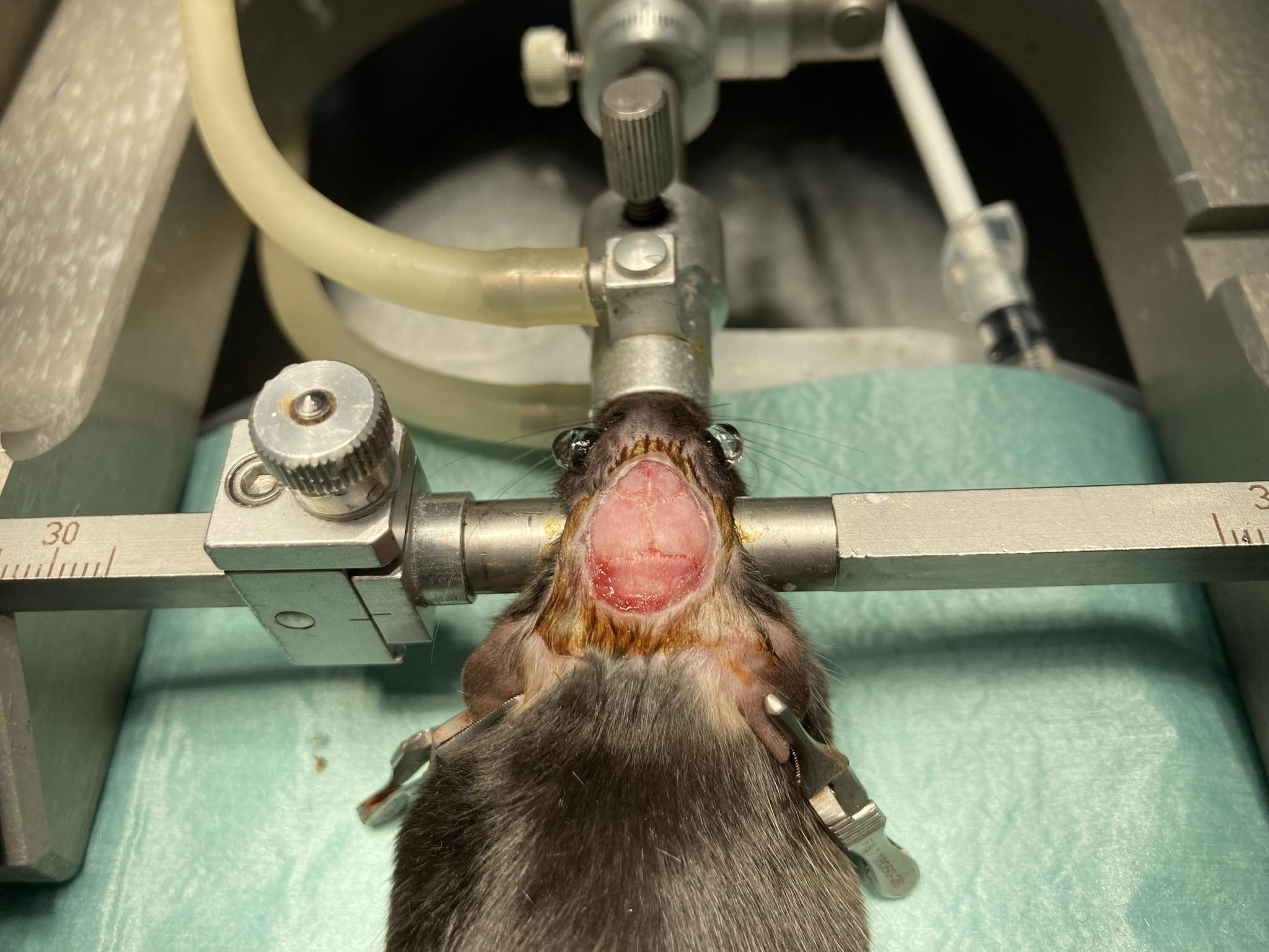
4. Head Incision and Exposure
Step 4: head incision and scalp exposure.
Using forceps and scissors, lift the scalp and remove a patch of skin to expose the top of the skull. This is where you will mount the EIF and insert the EEG electrodes.
For EMG recordings:
Extend the head incision a few millimeters beyond the skull to expose the trapezius muscles on the neck. Do not make a second incision-simply extend the original incision.
Expose both trapezius muscles, as the electrode will be implanted through both.
Apply Vetbond to the skin edges to prevent bleeding and to secure the skin in place. Avoid getting Vetbond in the eyes and on the exposed skull as you will be cleaning it shortly.
5. Skull Cleaning
Clean the skull surface thoroughly using a bone scrapper to remove the connective tissue.
Optional: apply diluted hydrogen peroxide (6% v/v) to the skull and immediately dry it. This highlights any remaining connective tissue on the surface of the skull that can be removed using a bone scrapper.
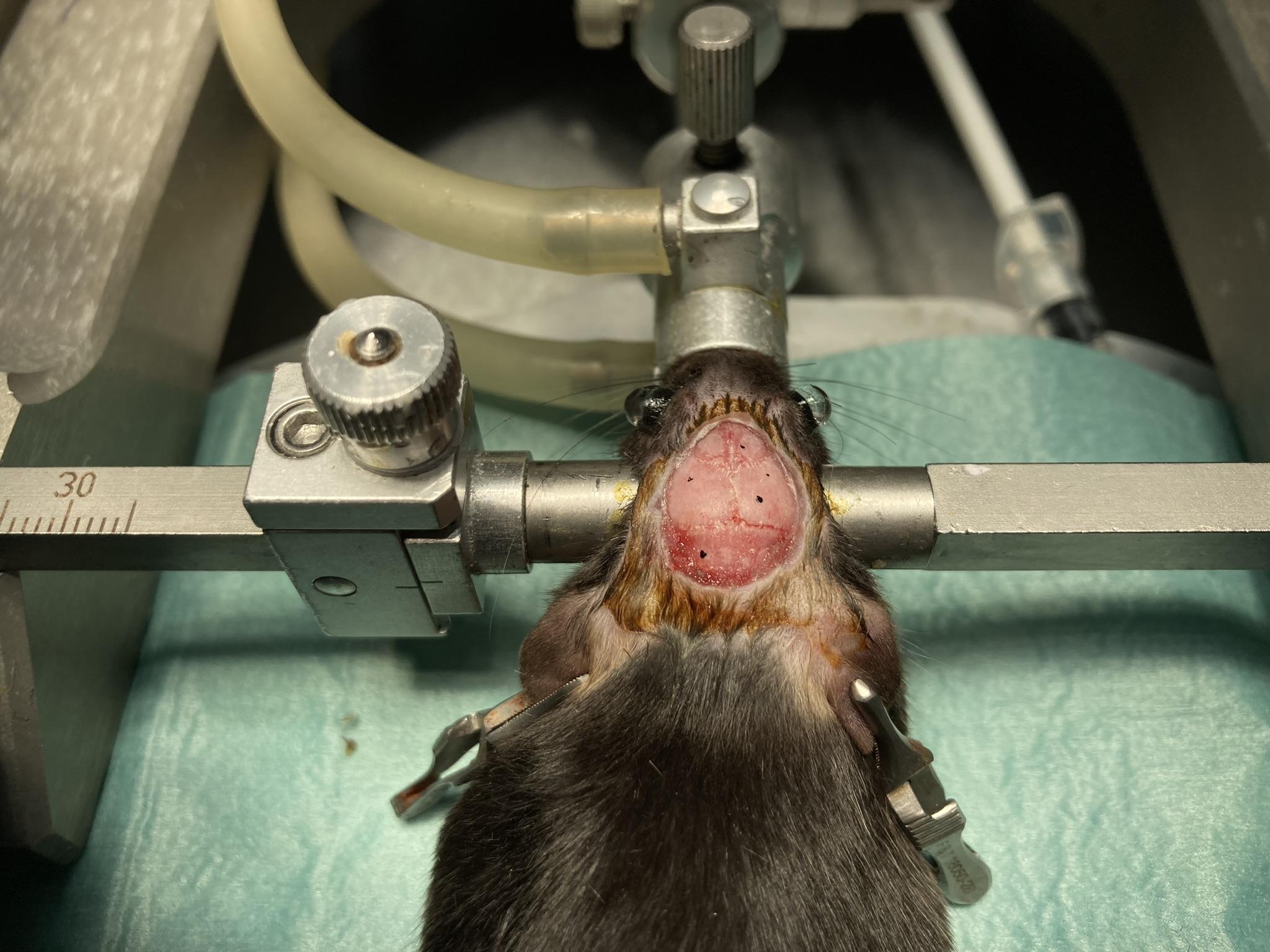
6. Burr Hole Mapping and Drilling
Step 6: Burr hole mapping.
Glue the skin of the scalp in place with Vetbond to prevent bleeding and keep skin retracted for surgery.
Zero the stereotaxic stand using bregma.
Using your stereotaxic apparatus, locate the desired burr hole coordinates, and mark them on the skull with a sterilized marker.
Carefully drill burr holes at marked positions. Stop until there is a thin layer of bone covering the dura. Use a sterile syringe needle or tweezers to pock through to the dura.
If using set screws to anchor electrodes, confirm their fit in the burr holes.
Dab excess fluid with sterile cotton.
Step 6: Testing the fit of the set screws.
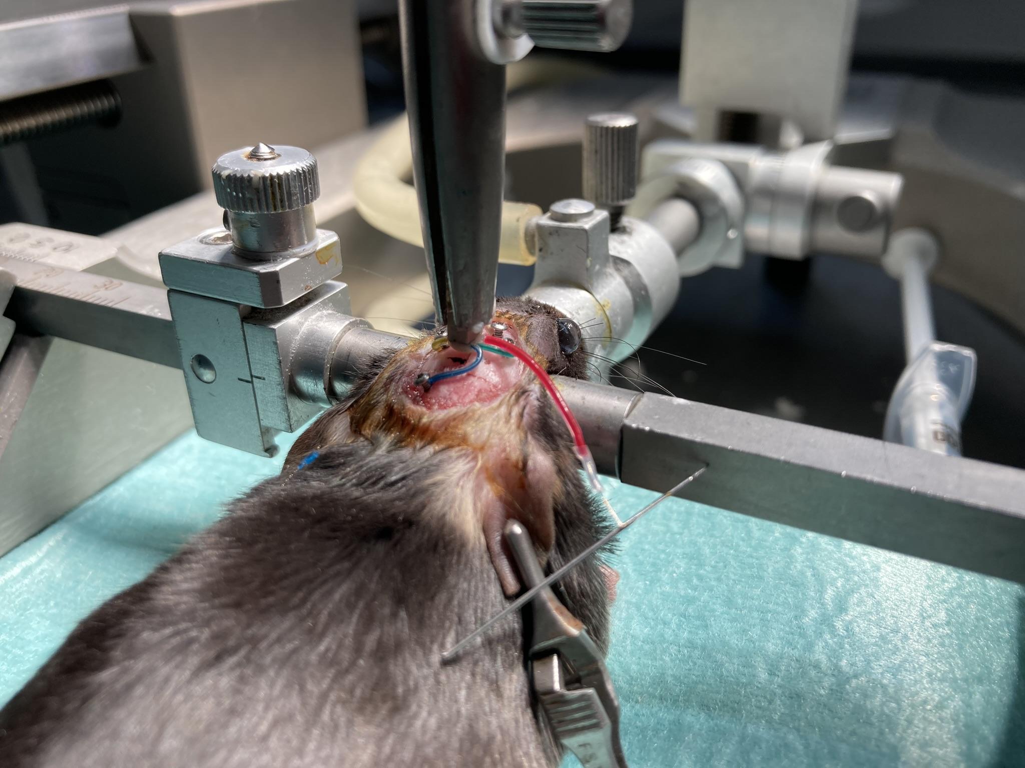
7. EIF Connector Placement
Step 7: EIF lowered to just above the scalp in order to measure and mark required lead lengths.Note: The EIFs are not reusable once implanted. The HMTs, however, are reusable.
Secure the EIF in the stereotaxic arm.
Align the EIF:
Anterior-posterior axis straight
Pins facing left (antenna should point backward)
Refer to the EIF manual to ensure you know the purpose and identity of each lead.
Lower the connector such that the bottom of the connector just touches the skull.
Remount the EIF to the previous positions (i.e., touching the skull) and apply a small amount of dental cement under the connector. This is to secure the EIF in place on the skull. Precaution must be taken to avoid the flow of the detal cement into the burr holes.
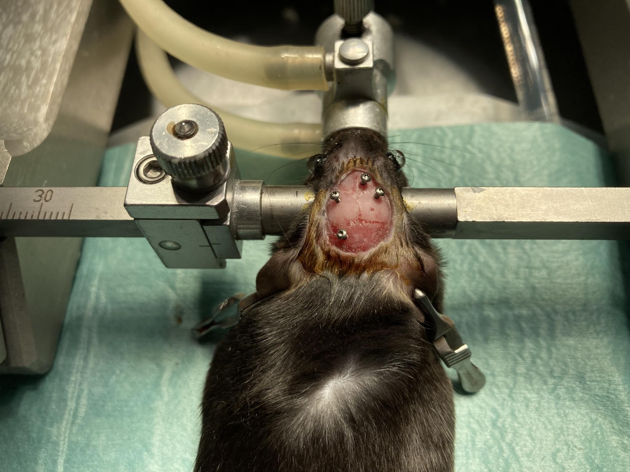
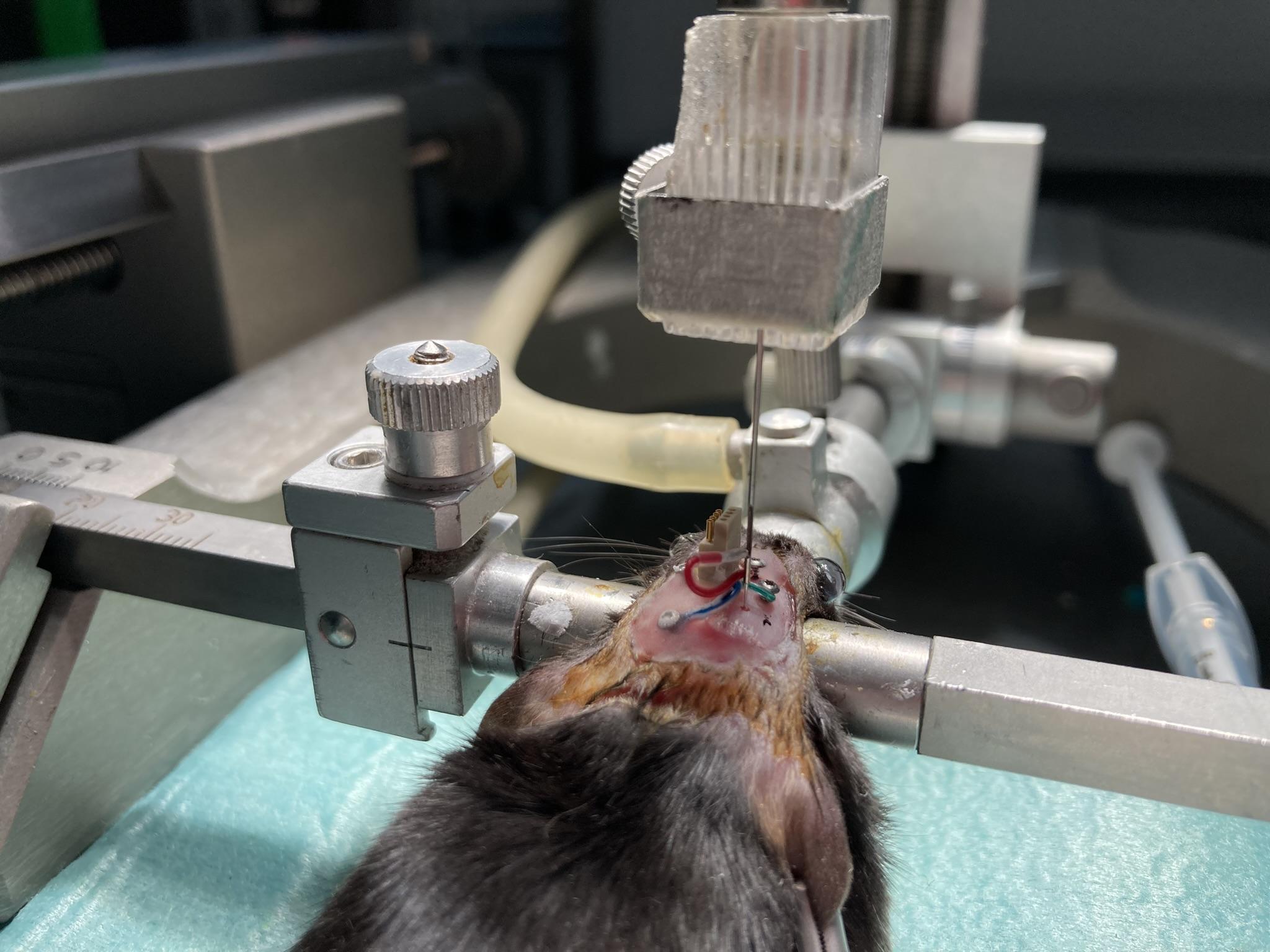
8. EEG Electrode Placement
Step 8: Surface electrodes and accompanying set screws implanted, depth electrode not yet implanted.
Insert all EEG surface electrodes electrodes into the brain before inserting any depth electrodes:
Straighten the bare coiled wire carefully with tweezers, avoiding tension on the lead.
Create a 90 degree bend at the midpoint of the bare wire.
Trim the bent section so it matches skull thickness plus desired cortical depth.
Test screw fit in burr holes; holes should be slightly smaller for a snug fit.
Insert the electrode into the burr hole, securing it with tweezers.
Leave a short section of exposed wire atop the skull (before the bend) to prevent screw contact with insulation.
Optionally apply Vetbond to the leads to secure them to the skull before screwing in the set screws.
Insert the screw into the burr hole, ensuring the electrode does not bind in the threads.
Secure screws with Vetbond now before applying dental cement.
Cover the screw and exposed wire with dental cement to insulate and reduce EEG artifacts.
Insert depth electrodes: consult our Electrode Surgery Protocol for instructions on implanting our various types of depth electrodes
Wrap excess leads around the EIF to reduce protrusion.
Notes
Ensure cement is fully dry before closure.
Position screws several millimeters away from insulated lead sections.
Wrap excess leads around the EIF to reduce protrusion.
Step 8: All EEG electrodes implanted and in place. Vetbond coating over set screws.
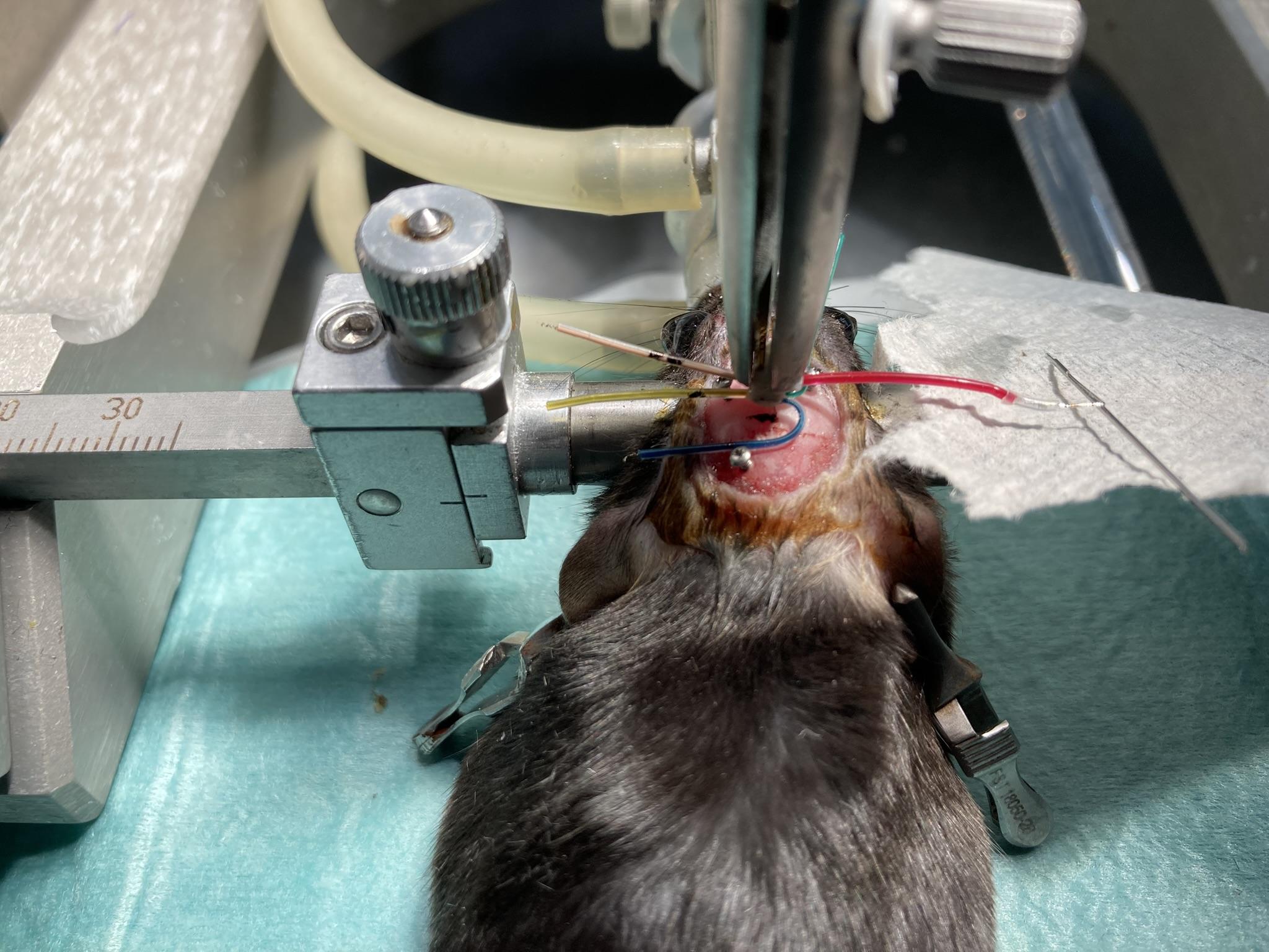
9. EMG Electrode Placement
Figure: Surgical diagram demonstrating the surgical insertion of EMG leads into the neck of a rodent. In this diagram, the syringe needle use to create one of the tunnels in the musle is still in place, with an EMG lead threaded through the needle. Note the direction of the syringe needle in relation to the lead.
Identify the top of the trapezius muscles at the base of the skull and locate the midline between them.
You will implant to EMG electrode into the neck. The green and yellow leads. The procedure for implanting and securing the EMG electrode is the same for both leads.
Use a pointed syringe needle to two ~2 mm horizontal tunnels through the trapezius muscles, try to go through both muscles. Begin the insertion on the side of the neck opposite the EMG lead, so that the hub (base) of the syringe needle is on the side of the neck furthest from the lead connection on the EIF, also known as the "exit" of the tunnel. This orientation allows you to remove the needle later by gripping the hub while holding the wire in place.
The needle does not need to go more then a few mm deep into the muscle. It must go deep enough that it can not easily be ripped out of the skin. The needle should create a "tunnel", meaning it should have both and entrance and an exit into the muscle.
Control bleeding with sterile cotton if needed.
Leave the needle in place.
With the syringe still in the muscle, insert the stripped coiled wire (e.g., lead with P
-Coil terminus) of your EMG lead through end of the needle. Thread the wire through until it exits from the other end of the muscle tunnel, leaving 1-2mm exposed and on top of the muscle.
10. Securing the EMG Electrodes
Figure: Surgical diagram demonstrating the surgical insertion of EMG leads into the neck of a rodent. In this diagram, the syringe needle use to create one of the tunnels in the musle is still in place, with an EMG lead threaded through the needle. Note the direction of the syringe needle in relation to the lead.
Ensure 1-2 mm of the bare wire protrudes from the muscle on the exit side before removing the needle.
Carefully remove the needle while keeping the wire in position. It is helpful to have the wire extend past the end of the needle a small amount, so you can grip it with tweezers while removing the needle.
Once the needle is removed, use tweezers to attach the OSI-provided wire cap to the exposed end of the wire at the exit of the tunnel. The wire cap should cover all of the exposed coiled wire that sits on the muscle. The purpose of the cap is to insulate the exposed electrode wire, reducing the risk of artifacts in the EMG signal.
Optional: Use a small amount of Kwik-Cast sealant to secure the cap. Be careful not to allow any sealant to drip into the muscle tunnel.
Place a few sutures over the capped wires, at the exit of the tunnel, to anchor it in the muscle and hold the cap in place on the exposed wire.
Suture the subcutaneous leads at the muscle entry point to prevent movement of the implanted wire.
Optional: Apply a small amount of dental cement to the portion of the lead before it enters the muscle to reduce movement under the skin. Avoid excess cement, which may restrict neck mobility.
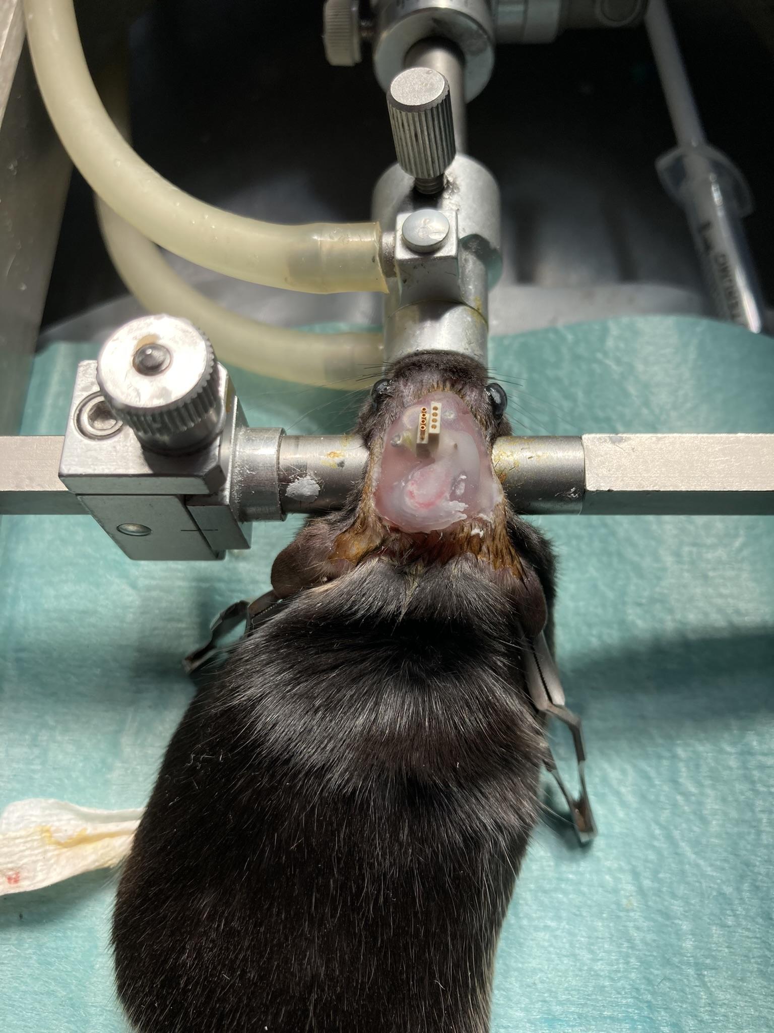
11. Securing EIF Implantation
Step 11: EIF and EEG electrodes implanted and attached, then covered with dental cement.Note: Do not close the animal up by suturing the skin back together on the head, rather, we reccommend creating a head fixture out of dental cement to secure the EIF and cover the electrodes. You will not attach the HMT until the animal recovers from surgery. This means the EIF will be sitting exposed on the animals head for a few days and needs to be covered in some way to protect from debris and damage.
EMG electrode and lead:
Ensure the electrode is secure and all adhesives are fully cured.
Verify there is some slack in the EMG lead to accommodate head and neck movement during recovery.
Close the incision over the EMG site by suturing the skin up to the base of the skull. While you can use dental cement to secure the EMG electrode implantation, dental cement on the neck can restrict the animals movement.
Apply dental cement to secure electrodes and connector base.
Cover exposed leads and skull surface-avoid covering the connector top.
Allow cement to fully cure and trim excess.
Cover the EIF top with tape/parafilm and optionally Kwik-Cast to protect it from debris and dislodging while the animal recovers and the HMT is not yet connected.
12. Surgical Recovery
Allow several days of recovery in a qiet, clean environment.
Monitor for pain, distress, weight loss, or infection.
Consult your vet for protocols on antibiotic treatments.
If the dental cement cap detaches or electrodes become exposed, consult a vet immediately-euthanasia may be required.
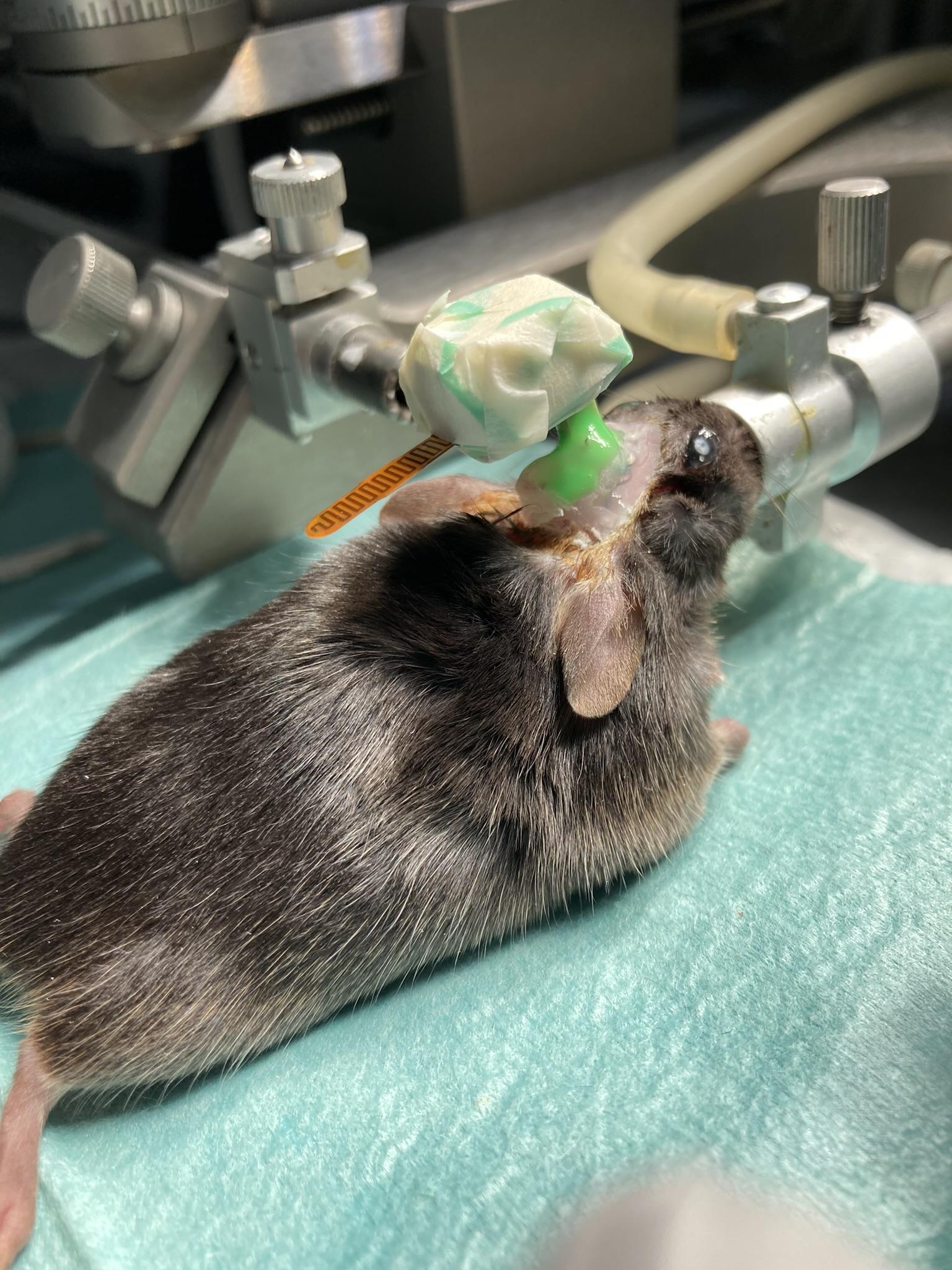
13. HMT Attachment
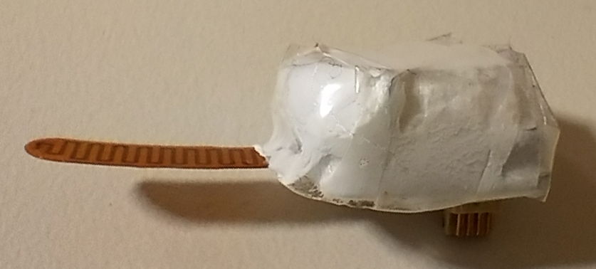
Step 13: The HMT fully attached to a mouse head, with a Kwik-Cast sealant.
Discharge you body of any electric static before handling the bare HMT, if possible.
Prepare the HMT:
Confirm the HMTs connection to the telemetry system.
Wrap the HMT in 2-3 layers of teflon tape, do not cover the connector.
Wrap the HMT in one layer of transparent tape and one layer of clear plumbers tape.
Briefly re-anesthetize the animal.
Attach the HMT to the EIF connector.
Secure the connection with Kwik-Cast.
Confirm electrical contact and alignment.
Monitor for scratching or attempts to dislodge the device.
14. HMT Replacement
Note: Replacement can be done with or without anesthesia. Some users prefer anesthesia to reduce stress.
Carefully remove Kwik-Cast from the old HMT.
Gently disconnect it from the EIF.
Attach the partner HMT (identical configuration and channel) to the EIF.
Secure the new HMT with Kwik-Cast
Return the animal to housing monitor its recovery.
Unwrap the original HMT and remove the battery by gently pushing it out with a wooden applicator.
15. Battery Replacement
Note: Only insert the new battery into the HMT right before surgery, otherwise it can damage the HMT and drain the battery.
Load a new battery just before use.
Clean the HMT before use:
Scrub with hot water and toothbrush
Soak briefly in ethanol make sure to thoroughly clean it.
Dry with compressed air (20 psi) if available
Wear sterile gloves when loading the new battery.
Wrap the HMT with Teflon and transparent tape.
Notes and Best Practices
Maintain sterility of all tools and materials.
Use minimal cement beneath the connector.
Avoid getting Vetbond on fur or unintended skin areas.
Carefully document electrode coordinates and placements.
Do not co-house animals with HMTs; they may remove each other's transmitters.
EMG electrode and lead:
Ensure the electrode is secure and all adhesives are fully cured.
Verify there is some slack in the EMG lead to accommodate head and neck movement during recovery.
Close the incision over the EMG site by suturing the skin up to the base of the skull. While you can use dental cement to secure the EMG electrode implantation, dental cement on the neck can restrict the animals movement.
 HMT Surgery Protocol, EEG and EMG
