Disclaimer: These protocols are intended as a guide for familiarization with the device and system.
Surgical and animal welfare guidelines vary by institution. Please consult your institution's veterinary professional
to ensure compliance with local regulations and protocols.
Purpose: This procedure specifically details the surgical implantation of electrodes for EEG and EMG recordings in mice and rats using either our SCT or HMT devices. This protocol does not cover the complete surgical
procedure for transmitter implantation.page-chunkmatch-prompts-onlyElectrode implantation for EMG and EEGWhat is the procedure for implantaing eletrodes in an animal?Surgical protocol for depth electrode implantation?
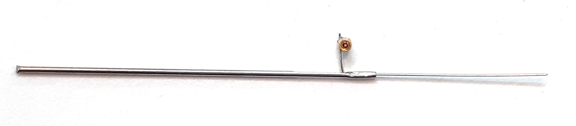
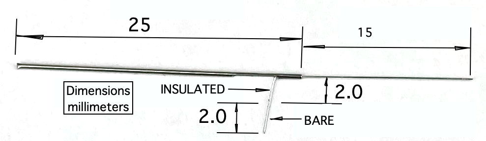
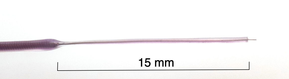
Our Depth Electrodes allow for a deeper reach into the brain. The insulated wire in the electrode will bve delivered either in the standard length or in a length specified by the you. You can cute the wire back to any length yourseld, either with a square cut or at an angle for better penetration. Each electrode provides a mounting fixture by which we can hold the electrode during surgery.
Stereotaxic apparatus with attachment to hold the metal electrode tube
Directions
Trim the insulated electrode wire to the desired length, based on the recording depth.
Secure the J-Electrode by its cannula guide in a clamp above the animal's head, mounted to a stereotaxic instrument for steady insertion.
Connect the D-Pin lead to the electrode socket.
Lower the electrode into the burr hole to the target depth.
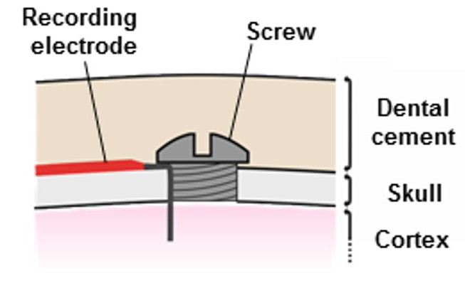
Seal the socket and burr hole with Vetbond adhesive followed by dental cement, or with cement alone. Avoid covering the cannula.
After the cement cures, cut the bare steel wire where it emerges from the cannula pedestal.
Lift the cannula off the wire.
Cut the wire flush with the cement surface and cover the exposed tip with additional cement.
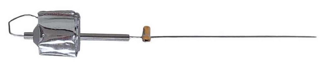
R-Electrode
Figure: R-ElectrodeNote: The R-Electrode is designed to allow repetead substance into the animals brain. The guide cannula remains on the animals head throughout the experiment.
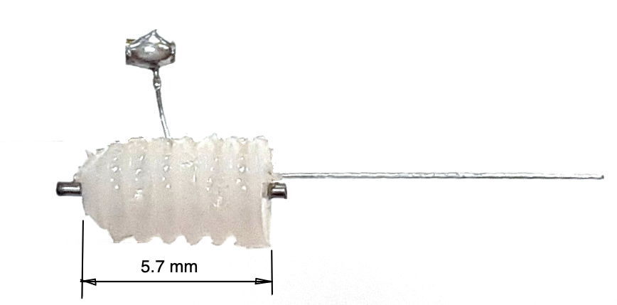
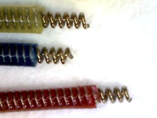
Confirm the EMG leads (connected to the SCT or HMT) have 3-4 mm of exposed coiled wire. Strip additional silicone if necessary (lead stripping video).
Verify the exposed coils fit through the selected syringe needles.
Sterilize all tools and materials before use.
2. Head Incision and Exposure
Use forceps and scissors to lift the scalp and remove a section to expose the skull.
For EMG, extend the head incision slightly beyond the skull to expose trapezius muscles, do not make a separate incision.
Expose both trapezius muscles for electrode placement.
Remove connective tissue from the skull and clean with diluted (6% v/v) hydrogen peroxide, then dry immediately. Remove residual tissue with a bone scraper.
3. Transmitter Device Implantation
For SCT: Follow the SCT Surgical Protocol to implant the transmitter and tunnel the leads before EMG placement. Ensure the EMG lead is pre-cut, stripped, and has adequate slack.
For HMT: Follow the HMT Surgical Protocol to attach the EIF connector and prepare EEG burr holes. Ensure the EMG lead is longer than EEG leads so it can reach the muscle in the neck
Refer to the EIF manual to ensure you know the purpose and identity of each lead.
8. EMG Electrode Placement
Figure: SCT Surgical diagram demonstrating the surgical insertion of EMG leads into the neck of a rodent. In this diagram, the syringe needle use to create one of the tunnels in the musle is still in place, with an EMG lead threaded through the needle. Note the direction of the syringe needle in relation to the lead.
Identify the top of the trapezius muscles at the base of the skull and locate the midline between them.
You will implant to EMG electrode into the neck. The green and yellow leads. The procedure for implanting and securing the EMG electrode is the same for both leads.
Use a pointed syringe needle to two ~2 mm horizontal tunnels through the trapezius muscles, try to go through both muscles. Begin the insertion on the side of the neck opposite the EMG lead, so that the hub (base) of the syringe needle is on the side of the neck furthest from the lead connection on the EIF, also known as the "exit" of the tunnel. This orientation allows you to remove the needle later by gripping the hub while holding the wire in place.
The needle does not need to go more then a few mm deep into the muscle. It must go deep enough that it can not easily be ripped out of the skin. The needle should create a "tunnel", meaning it should have both and entrance and an exit into the muscle.
Control bleeding with sterile cotton if needed.
Leave the needle in place.
With the syringe still in the muscle, insert the stripped coiled wire (e.g., lead with P
-Coil terminus) of your EMG lead through end of the needle. Thread the wire through until it exits from the other end of the muscle tunnel, leaving 1-2mm exposed and on top of the muscle.
10. Securing the EMG Electrodes
Figure: SCT Surgical diagram demonstrating the securement of EMG leads inthe neck of a rodent. In this diagram, you can see the electrode caps place on the exposed wire that exits the tunnel through the muscle. The cap is secured either by and additional suture over the cap, or with Kwik Cast (either in the cap or over the cap and lead).Figure: HMT Surgical diagram demonstrating the surgical insertion of EMG leads into the neck of a rodent. In this diagram, the syringe needle use to create one of the tunnels in the musle is still in place, with an EMG lead threaded through the needle. Note the direction of the syringe needle in relation to the lead.
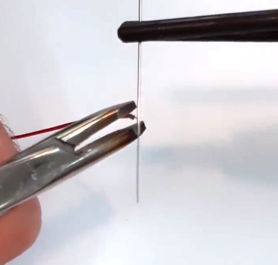
Ensure 1-2 mm of the bare wire protrudes from the muscle on the exit side before removing the needle.
Carefully remove the needle while keeping the wire in position. It is helpful to have the wire extend past the end of the needle a small amount, so you can grip it with tweezers while removing the needle.
Once the needle is removed, use tweezers to attach the OSI-provided wire cap to the exposed end of the wire at the exit of the tunnel. The wire cap should cover all of the exposed coiled wire that sits on the muscle. The purpose of the cap is to insulate the exposed electrode wire, reducing the risk of artifacts in the EMG signal.
Optional: Use a small amount of Kwik-Cast sealant to secure the cap. Be careful not to allow any sealant to drip into the muscle tunnel.
Place a few sutures over the capped wires, at the exit of the tunnel, to anchor it in the muscle and hold the cap in place on the exposed wire.
Suture the subcutaneous leads at the muscle entry point to prevent movement of the implanted wire.
Optional: Apply a small amount of dental cement to the portion of the lead before it enters the muscle to reduce movement under the skin. Avoid excess cement, which may restrict neck mobility.
7. Closing
Follow SCT or HMT closing protocols.
Ensure electrodes are secure and adhesives are fully cured.
Leave slack in the EMG lead to accommodate head and neck motion.
Close the incision by suturing up to the skull base.
Complete the dental cement cap procedure as per SCT or HMT protocols.
Notes and Best Practices
When reusing SCT leads, re-strip the silicone cleanly (video guide).
Avoid filling burr holes with Vetbond, particularly for depth electrodes, which do not fully occupy the hole.
 Electrode Surgery Protocols, EEG and EMG