| Description |
| Light Sources |
| Electrodes |
| Operation |
| Implantation |
| Heating |
| History |
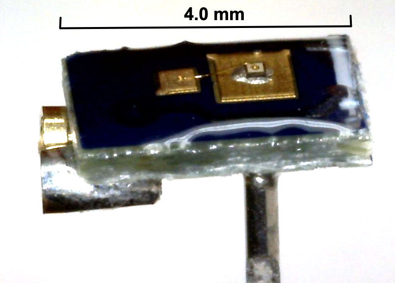
[25-MAY-26] Our implantable stimulators are designed to provide electrical or optical stimulation for laboratory mice and rats. They provide pulses of current for direct electrical stimulation and they provide pulses of current for optogenetic stimulation by means of our Implantable Light-Emitting Diodes (ILEDs). The A3041 Implantable Stimulator-Transponder (IST) is designed for long-term experiments that require intermittent stimulus. It comes in various sizes and configurations, and it hosts a crystal radio, telemetry transmitter, current source, and embedded microprocessor. When deployed as an electrical stimulator, the IST stimulus leads will be terminated with pins that connect to a bipolar Subcutaneous Depth Electrode (SDE). When deployed as an optogenetic stimulator, the stimulus leads will be terminated with pins that connect to an ILED.
All our implantable stimulators responds to radio-frequency commands transmitted using the same radio-frequency band that our telemetry system uses for reception of telemetry signals from implanted and head-mounted sensors. Our implantable stimulator-transponders can also transmits telemetry signals, although these consist of synchronizing traces and acknowledgements rather than the digitized biopotentials transmitted by our telemetry sensors. To command an IST we use a command transmitter. The A3042B-16 Telemetry Control Box (TCB) is a combined telemetry receiver and command transmitter. All sixteen of its coaxial antennas transmit commands simultaneously, ensuring robust reception of commands in the entire volume of our telemetry system. These commands will be brief and rare in a typical stimulator experiment. At all other times, the same sixteen antennas will be dedicated to telemetry reception. The A3042B-16 went into production in 2024. We expect smaller A3042B-4 to go into production in late 2026. Prior to its arrival, we commanded ISTs with the A3029C Command Transmitter, a device we continue to support, and which we still have on the shelf, but which we no longer manufacture.
Our implantable stimulators provide stimulation, acknowledgement, battery monitoring, synchronizing signal, and user-program upload all by radio control. It receives commands through its loop antenna using its on-board crystal radio. It transmits signals through the same antenna using our Subcutaneous Transmitter (SCTs) telemetry protocol. Our SCTs, meanwhile, provide wireless, long-term, continuous monitoring of biopotentials to accompany intermittent stimulation. When we have both a sensor and a stimulator implanted in an animal, we can generate stimuli in response to sensor events. This real-time response to sensor data with a stimulus is what we call closed-loop control. Watching for seizure onset in EEG, and responding to seizure onset with twenty seconds of electrical pulses applied to the brain, is an example of a closed-loop system.
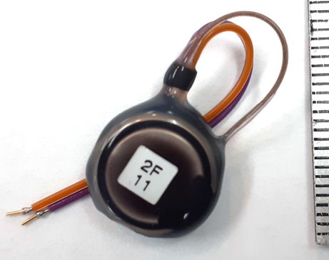
For electrical stimulation, the A3041 Implantable Stimulator-Transponder drives a bipolar stimulation electrode with constant-current pulses. For optical stimulation, it drives one of our implantable LEDs with pulses of current. Our Clear-Epoxy Light-Emitting Diodes (CE-LEDs) come in red, green, and blue. These are designed to be fastened to the surface of an organ and illuminate the tissue within. Our fiber-coupled implantab le light-emitting diodes come in two varieties: the tapered-fiber TF-LED and the blunt-fiber BF-LED. The TF-LED is designed to be mounted on the skull of a rat or mouse and illuminate deeper brain tissue. The BF-LED is designed to mount on the skull of a rat. Instead of penetrating brain tissue, the BF-LED delivers light through the skll to the surface of the brain without penetrating the dura.
[20-MAR-26] Our Implantable Light-Emitting Diodes (ILEDs) provide optical stimulation for experiments in optogenetics. Our Clear-Epoxy Light-Emitting Diodes (CE-LEDs) come in red, green, and blue. They are designed to be fastened to the surface of an organ and illuminate the tissue within. Our Tapered-Fiber Light-Emitting Diodes (TF-LEDs) and Blunt-Fiber Light-Emitting Diodes (BF-LEDs) come in green and blue. They are designed to be anchored to the skull and provide illumination deeper in the brain.
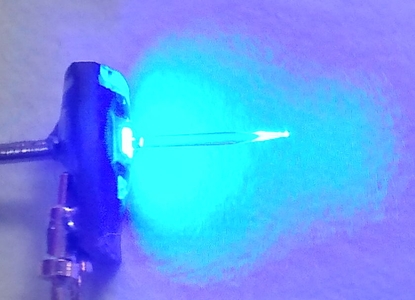
All ILEDs are equipped with sockets that accept the pins at the end of stimulator leads. To implant the stimulator and ILED for brain stimulation, we make an incision in the flank of the animal for the stimulator, tunnel the wires with pins under the skin to the animal's skull, and connect the pins to our ILED, which we then cement in place. The TF-LEDs are an implantable light-emitting diode with a fiber-optic light guide glued to its surface. The light guide carries roughly half the LED's light a to a tapered glass tip, where the light is emitted in all directions. The light guide can be four to ten millimeters long. It allows us to deliver optical stimulation to tissue several millimeters below the surface.
For the TF-LED we make a small hole in the skull for the fiber to pass through and cement the base of the fiber to the skull. For the CE-LED we make a larger hole so that we can mount the epoxy dome of the CE-LED directly in the hole. A blue TF-LED required only 1-ms pulses of 15 mA at 10 Hz to provoke optogenetic response, while a blue CE-LED required 10-ms pulses of 15 mA at 10 Hz.
[20-MAR-26] For electrical stimulation, we can use any of the electrodes or terminations in our Electrodes and Termination catalog. We have not yet manufactured a twisted pair of stainless steel wires for a bipolar stimulation electrode, but we understand that such electrodes are commonly deployed for electrical stimulation, and we will be happy to design and build one for an interested customer.
[20-MAR-26] The A3042-B Telemetry Control Box (TCB) needs only one Power over Ethernet (PoE) connection for power and communication. The A3042B-16 provides sixteen coaxial antennas that by default receive telemetry signals, but will transmit commands simultaneously when instructed to do so. The A3042-B4 provides four such antennas. The A3029C Command Transmitter is a standalone command transmitter suitable for deployment with an A3027E Octal Data Receiver and a A2071E LWDAQ Driver. This combination of three devices: a heavy silver chassis, a large silver box, and a black box, is complicated to set up and provides only one command antenna. Although we still have A3029C command transmitters on the shelf, we recommend that users of our ISTs switch to the A3042-B4 or A3042B-16 Telemetry Control Box and retire their A3029C Command Transmitters. In either case, the Stimulator Tool built into our LWDAQ Software provides the computer interface we need to program and control the ISTs, and the Stimulator Tool Manual describes how to set up both types of system.
With the Stimulator Tool, we define a stimulus by specifying a number of pulses, the length of each pulse, and the period of the pulses. One minute of 10-ms pulses at 10 Hz would be 600 pulses, each 10 ms, with period 100 ms. We specify the current of the pulses with another number between zero and fifteen. Consult the IST circuit manual for how these numbers relate to the current and voltage limits of the stimulus. We specify if the stimulus is to be random or regular. In a random stimulus, the pulses can occur anywhere within each period window, at random. We find that random stimuli do not invoke optogenetic response, while regular stimuli do. Random stimuli have the potential to act as a control stimulus.
The Stimulator Tool allows us to request acknowledgements for each command, in which case the Receiver Instrument, i it is running, will pick out the acknowledgement and the Stimulator Tool will confirm that the command was received. The Stimulator Tool will also transmit a general identification request that all ISTs in range will respond to by transmitting their identity numbers. The Stimulator Tool will transmit a battery measurement requests as well, and present the results of the measurement.
Each IST contains its own OSR8 microprocessor running a main program, but also capable of running code provided by its user. The Stimulator Tool also allows us to assemble, upload, and run programs on an IST. These programs are written in the OSR8 assembly language. The Stimulator Tool manual provides example code. Editing, testing, uploading and running user programs is simple with the Stimulator Tool's built-in Transmit Panel. The A3041 stimulator provides 2 KByte of volatile user-program memory. When the A3041 goes to sleep, it forgets its user program, so we must upload it again as part of our experimental procedure. Future ISTs will provide non-volatile user program memory so that we can upload complex programs and have them be available as soon as the IST wakes up.
[20-MAR-26] We implant the IST subcutaneously, and tunnel its leads to the stimulus location. Most often, we will equip the leads with pins that will plug into sockets on a bipolar electrical stimulus electrode, or plug into an implantable light-emitting diode (ILED).
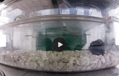
If we are performing an optogenetic experiment with an ILED, we may also be recording EEG or some other biometric signal with an SCT implanted separately in the same animal. If so, we must make sure the ILED drive signal does not corrupt the sensor signal with what we call stimulus artifact. We plug the stimulator pins into the ILED, cover them with a thin layer of dental cement or vetbond, lower the ILED into position, and cover thoroughly with dental cement to secure the ILED and further insulate its stimulus pins from the rest of the body. With care, we can provide insulation adequate to reduce the stimulus artifact to below a few microvolts. If we are not careful, the stimulus artifact can tens of microvolts. For an explanation of how stimulus artifact arises even when we have separate implants, see Sources of Lamp Artifact. For video and EEG recordings made with an IST and SCT during optogenetic response, see Examples of Optogenetic Response
[11-MAY-26] All but the smallest of our A3041 Implantable Stimulator-Transponders, when connected to an A3036 Tapered-Fiber Light Emitting Diode (TF-LED), are capable of overheating the brain. Light scatters through brain tissue, but is ultimately absorbed within a few millimeters of its source. Assuming an absorption volume of radius 1 mm, we would like to know how much light we can shine into this volume, and for how long, before we raise its temperature by 1 Kelvin = 1 K = 1°C. There are three parts to this calculation: the rate at which blood can transport heat, the rate at which conduction can transport heat, and the rate at which brain tissue itself warms with the arrival of heat. We will address all three in the paragraphs below. We assume that the density, specific heat capacity, and thermal conductivity of blood and brain are the same as that of water: 1 mg/mm3, 4.2 μJ/μg/K, and 600 μW/mm/K respectively.
According to the article Cerebral circulation, blood perfusion in the human brain is roughly 50 ml per 100 g per minute. Assuming the same value for smaller mammalian brains, we have roughly 0.01 mg/s through each 1 mg of brain tissue in rats and mice. Suppose we deliver 10 mW of blue light to the brain with a Tapered-Fiber Light Emitting Diode (TF-LED). We choose 10 mW for our calculation because it is the approximate power by the tip of a 270-μm diameter blue TF-LED with forward current 30 mA, and 30 mA is the maximum current our stimulators can deliver. Almost all blue light is absorbed by brain tissue within 1 mm of its source, so we will be illuminating π * (1 mm)2 * 4 / 3 ≈ 4 mm3 = 4 mg of brain tissue with the light from the fiber tip. This 4 mg of tissue has 40 μg/s of blood flowing through it. If we ignore conduction of heat through the brain, assume thermal equillibrium has been attained, and assume all heat is transported away by blood, this 40 μg/s will warm by 10 mW / 40 μg/s / 4.2 μJ/μg/K = 60 K. If we want blood flow to stop the brain warming by more than 1 K, the average blue-light power we emit from our TF-LED must be less than 10 mW / 60 = 170 μW.
We see that heat transport by blood flow can carry away no more then 170 μW from our illuminated sphere of brain tissue before the tissue warms by 1 K. Let us consider transport by conduction. Our 1-mm radius sphere of illuminated tissue has surface area 4 * π * (1 mm)2 * ≈ 12 mm2. In order to transport 10 mW through this surface, we need a temperature gradient of 10 mW / 12 mm2 / 600 μW/mm/K = 1.4 K/mm in the radial direction. If we transport the heat to a radius of 5 mm, the mass of tissue containing the heat will be π * (5 mm)3 * 4 / 3 * 1 mg/mm3 ≈ 500 mg, from which blood perfusion will remove 500 mg * 10 μg/s/mg * 4.2 μJ/μg/K = 21 mW/K. Once we get to 5 mm radius, warming by 0.5 K of the blood passing through the 5-mm sphere will remove the 10 mW of blue light power. In order to transport the blue light power to a radius of 5 mm, we a little more than 5 mm * 1.4 K/m = 7 K warming at the tip of the fiber, because the surface area for conduction close to the sphere is less. We estimate 10 K of warming at the fiber tip will be adequate to transport 10 mW away from the its immediate vicinity. If we want conduction to stop the brain warming by more than 1 K, the average blue-light power we emit from our TF-LED must be less than 1 mW.
Convection and conduction cannot stop 10 mW of blue light from heating the brain by 1 K. If we drive one of our 270-μm diameer blue TF-LED with 30 mA and emit 10 mW of blue light into the brain, we wonder how long can we leave the light on before the brain warms by 1 K. This 10 mW is warming the 1-mm radius sphere of brain tissue around the fiber tip. The mass of this sphere is roughly 4 mg. Its heat capacity is 4 mg * 4.2 mJ/mg/K = 17 mJ/K. The tissue will be warming at 10 mW / 17 mJ/K = 0.6 K/s. After 1.7 s the sphere has warmed the tissue by 1 K. Ignoring conduction and convection, if we want to warm the brain by no more than 1 K during a 20-s light pulse, we must emit no more than 0.85 mW, which means our maximum drive current to this particular TF-LED must be 2.6 mA. But convection does help us a bit, as does convection. And if we are shining the light through the intact skull of a mouse, we will get less than half the power to the brain, and that power will be distributed over a larger volume following scattering in the skull tissue. In such a trans-cranial illumination, we estimate that we will be able to deliver 10 mW for 20 s before the tissue warms by 1 K.
The above calculations could easily be wrong by a factor of three. Nevertheless, they are consistent with the experience of our collaborator, Professor Cenk Ayata, who tells us, "Yes, 10 mW for 30 sec caused coagulative necrosis in the cortex of mice through the intact skull, so we have been keeping the intensity and duration low or using trains. You can still trigger SD with trains. But the penetration depth of blue light in brain is not far, perhaps 500 microns or so, in case it changes your calculations."
[20-APR-26] Development of our implantable stimulators began in 2012 with the development of an Implantable Sensor with Lamp (ISL) for use in rats. Work on the ISL for rats was funded by the Wellcome Trust via Dimitri Kullmann at the Institute of Neurology (ION) at University College London (UCL). We collaborated with Dimitri Kullmann, Robert Wykes, and Matthew Walker, all of ION/UCL. The A3030 Implantable Sensor with Lamp was a failure in that we were unable to isolate the sensor input from the LED voltage. When implanted in an animal, we found the sensor signal was usually corrupted by stimulus artifact of at least 1 mVpp. In 2019 we began work on a mouse-sized implantable stimulator-transponder with funding from the Fitzgerald Laboratory at UCL and OSI's research budget, see IST Technical Proposal. This IST was the first device to include only a stimulator. In 2020 we began work on a mouse-sized ISL with the support of a Small Business Innovation Research (SBIR) Phase I grant from the National Institute of Health (NIH), in collaboration with the Schaffer Laboratory at Cornell University. The A3037 Implantable Sensor with Lamp was a success in that it was small enough to implant in a mouse and reduced the stimulus artifact to less than 100 μVpp. Nevertheless, when it came to initiating optogenetic response and recording electroencephalogram (EEG) in mice, we used IST in conjunction with SCTs, not the ISL. The separate SCT and IST guaranteed zero artifact, and the two small implants rather than one double-sized implant were no more difficult ti implant.
In 2022 our application for Phase II funding from the NIH was declined for the second time. The reviewers saw no particular need for the stimulator and sensor to be combined in one device, and we agree with them. The animal trials we conducted in 2021 at ION/UCL and Cornell University demonstrated that 1-ms, 15-mW pulses of blue light delivered by an TF-LED at 10 Hz were sufficient to invoke optogenetic response. Our expectation had been that 10-ms pulses would be required. With the stimulus power requirement ten times lower than we expected, we were able to switch from lithium-ion batteries as a power source to lithium primary cells. The latter have three times the charge capacity per unit volume as the former, allowing us to triple our operating life. In 2022, we used OSI's research budget to design and test the A3041 Implantable Stimulator-Transponder. The A3041, along with the A3036IL implantable LEDs, are the final result of our ten years of work on implantable stimulators. The A3041 is small, long-lasting, corrosion-resistant, and provides both electrical and optogenetic stimulation. We have abandoned our plans to make a combined sensor and stimulator, but you will find our old ISL page here.
In the summer of 2023 we assembled a set of A3041AV1 and worked on discovering bugs in their firmware and hardware. We found that the CR1025 battery is inadequate to power up the A3041AV1 assembly after a few weeks of implantation. We must use the larger CR1225 and CR1620 batteries. We discovered several other problems with the circuit, such as its inability to turn off after being asked to transmit a synchronizing signal of too high a sample rate. We solved all these problems and added to the A3041 the ability to receive and run user-programs. We reduced the hibernation current of the device to less than 1 μA and its sleep current to less than 5 μA. The result is what we believe to be a versatile and long-lasting implantable stimulator for intermittent stimulation experiments.
In the first quarter of 2026 we made significant improvements to the stability of the A3041 firmware, and discovered several ways in which future ISTs could be built with lower waking current and longer high-power stimulus operating life. We have no immediate plans to produce a new version of the A3041, or a replacement, because the existing circuit is so far satisfying our customers. But we have transferred the lessons learned to our second-generation telemetry sensor designs, such as the A3054 Intraperitoneal Transmitter (A3054). Another development in early 2026 was the Blunt-Fiber ILED, which allows us to deliver more power to the surface of the brain by transporting power through the skull to the brain surface.
In the Spring of 2026 we replaced CR-series lithium coin cells with LIR-series lithium-ion coin cells in all versions of the A3041 except the smallest, so that only the A3041A versions still use a CR-series battery. The LIR batteries have one third the charge capacity per unit mass as the CR batteries, but the LIR batteries can deliver full power to the ILED without suffering any internal damage, which greatly simplifies the operating constraints of the stimulator and greatly increases the time for which we can turn on the lamp.